
DaVinci Kiln Assembly Instructions
Rev: 1/1/2023
PLACEMENT, LOCATION & INSTALLATION
- The general Dimension Drawing of all kilns is on the webpage of each kiln model. These have ventilation and clearance requirements.
- Review our installation overview page for codes, clearances, ventilation, and electrical installation information before assembling your kiln.
INSPECTION
When Your Kiln Arrives
- Your kiln will arrive on two or three crated skids, depending on the model and accessories ordered.
- Inspect the skids for damage. If you notice any, either refuse the shipment or unpack the kiln in the driver’s presence so you can file a damage report with the freight company.
- Call our office if there is any damage. For more information, refer to the Shipping, Receiving & Inspecting Kilns page.
Unpack the Crates
- Carefully remove the crating boards from each skid.
- One crate contains the kiln stand, counterbalance, control panel, and additional accessories.
- The other crate(s) contain the kiln sections (stacked in reverse order for proper setup), the kiln top (lid), the kiln bottom (floor), and the aluminized plate that goes between the floor and the kiln stand.
ASSEMBLY
Set Up the Stand and Bottom
- Place the kiln stand on the floor in your desired location.
- Refer to the Preparation & Installation page for detailed information on local codes, ventilation requirements, and clearances.
- Put the flat aluminized plate on top of the kiln stand, then place the kiln floor on top of the plate.
- Note that the aluminized plate is packed directly under the kiln floor; you can move both pieces together onto the stand.
- Ensure the plate and floor sit flush and are properly centered on the stand.
- If a vent is supplied and must be attached to the bottom, do so now.
- Level the kiln.
- An unlevel kiln can also lead to cracking of the bottom or top.
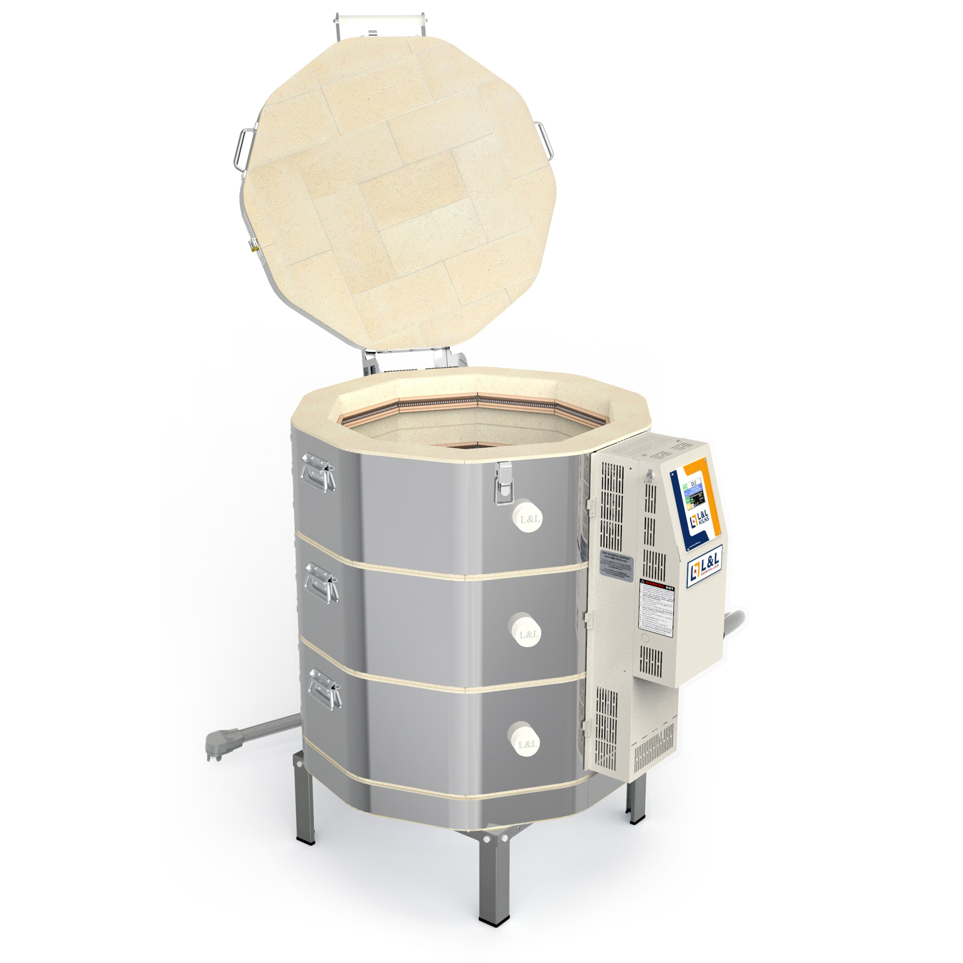
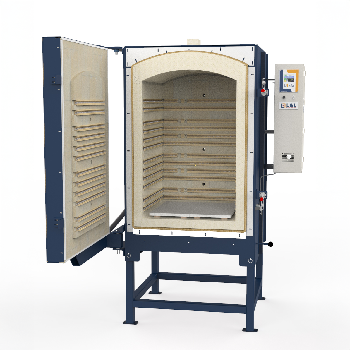
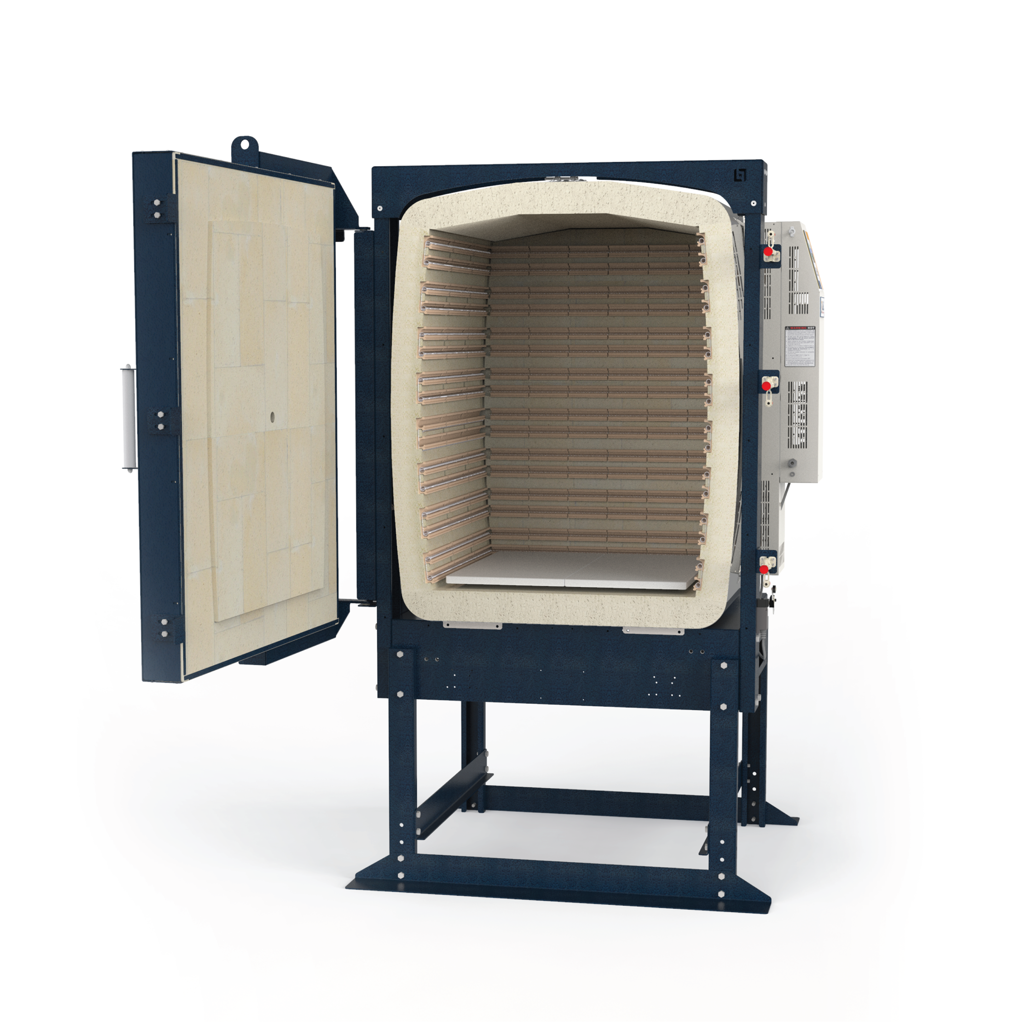
Stack the Kiln Sections
- Each kiln section has a numbered power cord (called an “element box jumper cord”): the top kiln section is always labeled “#1.” The bottom kiln section is “#2” on a two-section kiln, “#3” on a three-section kiln, and so on.
- Stack the sections in the correct order, ensuring the numbers match.
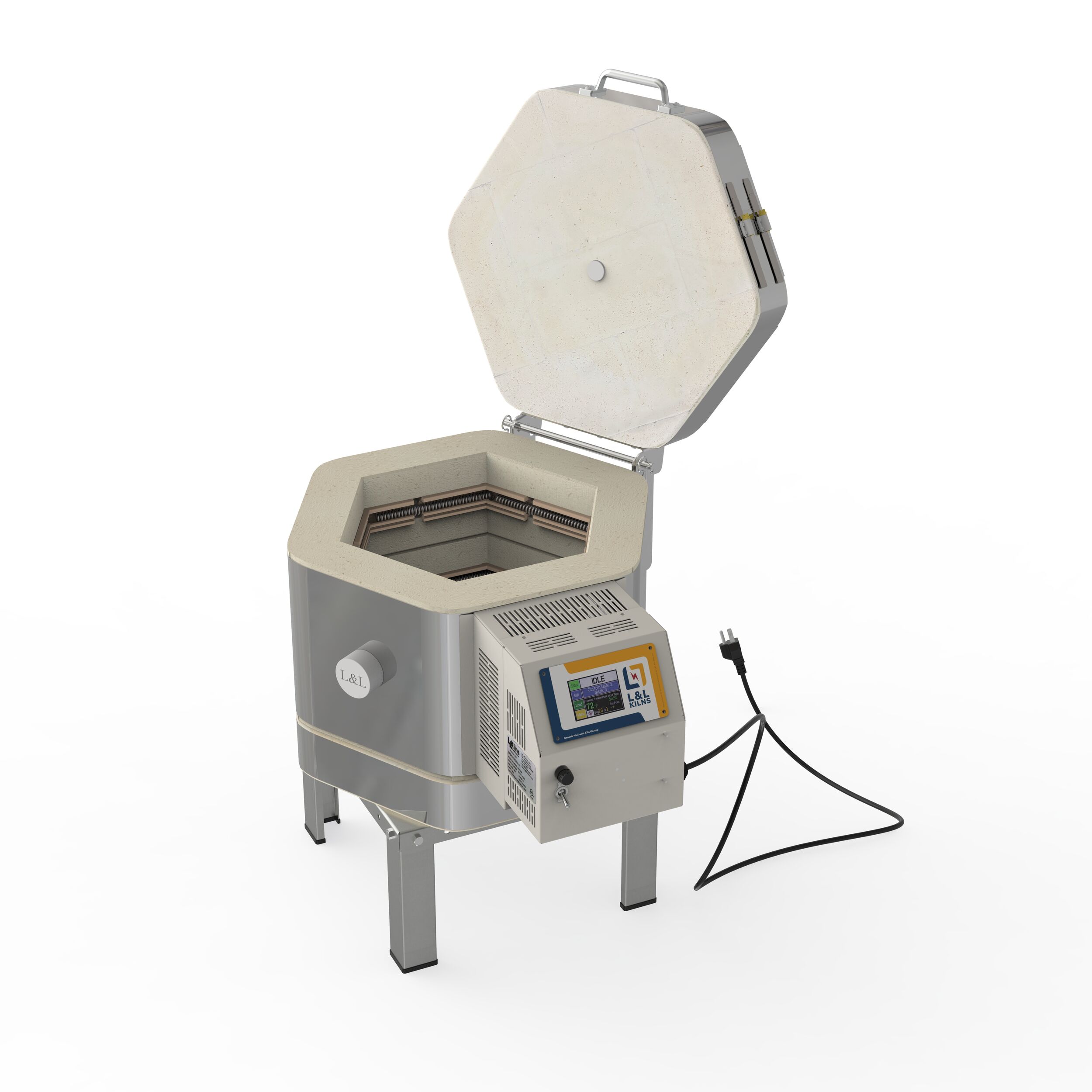
Lid Placement
- Remove the hinge bar and its hardware, then set them aside.
- Place the kiln lid squarely on the top kiln section.
- The lid is slightly larger than the kiln section; center it as evenly as possible to help when attaching the counterbalance.
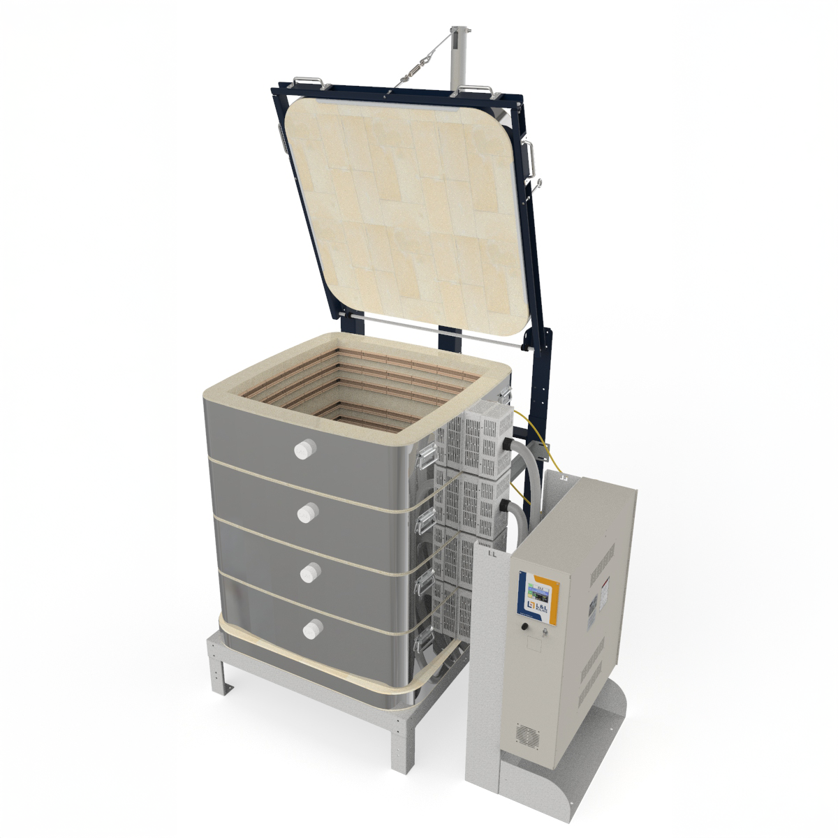
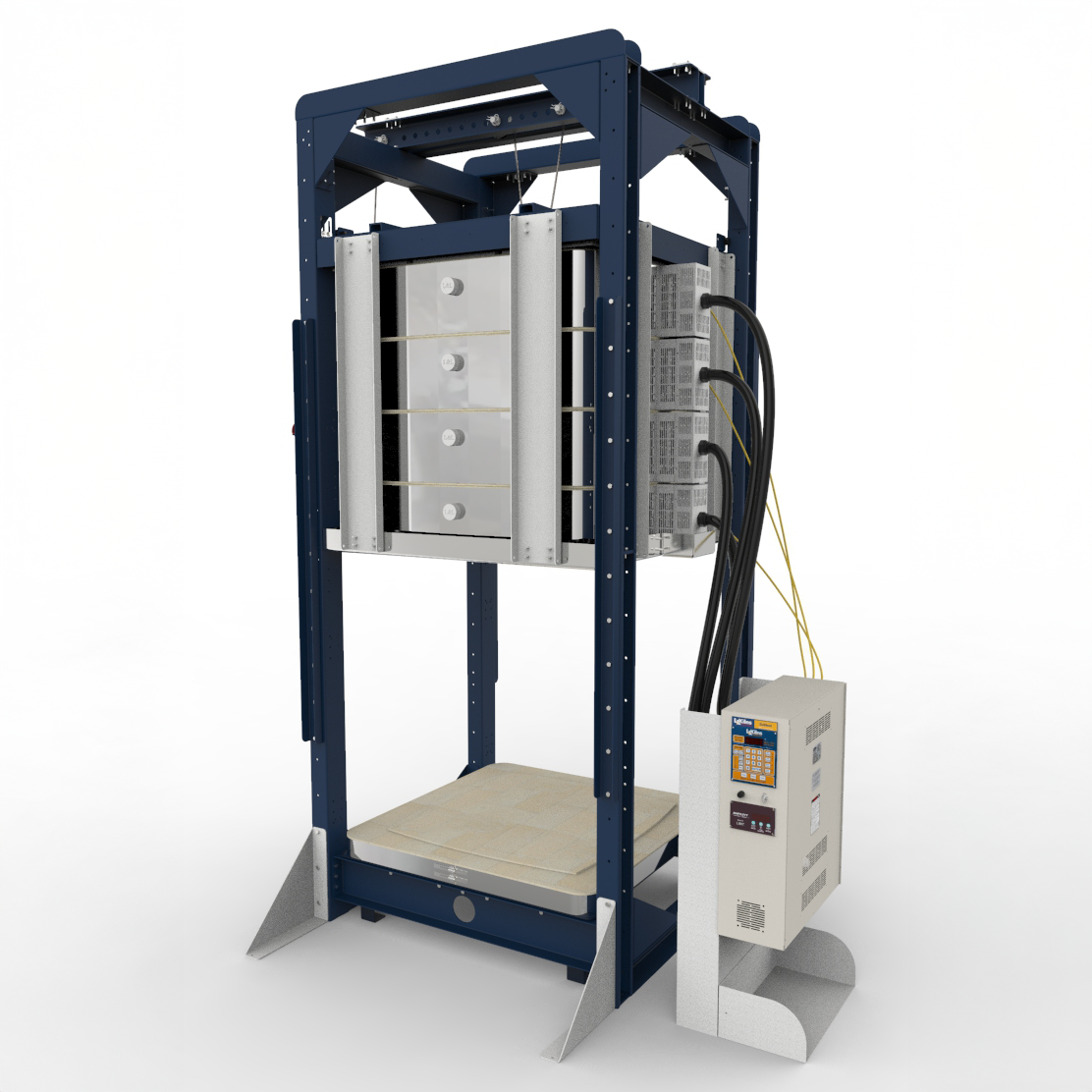
Attach the Counterbalance
- Remove the sixteen screws from the bottom and the third-from-bottom kiln sections.
- On a two-section kiln, these screws are located on the top and bottom sections.
- Position the counterbalance so that the holes in its arms align with those in the kiln sections.
- If the holes do not align, adjust the stacked sections until they do.
- Reinsert the sixteen screws to secure the counterbalance.
Assemble the Lid and Hinge
- Gently position the kiln lid so the oblong holes in the counterbalance’s pipe plates line up with the round holes in the lid’s side channels.
- The counterbalance pipe is factory-set so the round bar sits at the bottom of the pipe plate’s oblong hole.
- This allows the lid to pivot and to rise slightly as the kiln heats and the brick expands.
Attach the Lid to the Spring Cable
- If necessary, rotate the spring tubes so the cable exits at the top of each tube, facing the front of the kiln.
- Tighten the cable clamps that hold the spring tube to the angle (these may have been loosened for shipping).
- Position the spring tube safety brackets to face the back of the kiln.
- Lift the door and attach the safety chains to the eyebolts on each side of the kiln door.
- Open the oval connectors and connect the cable from the tubes to the cable adjusters on the eyebolts in the front of the door.
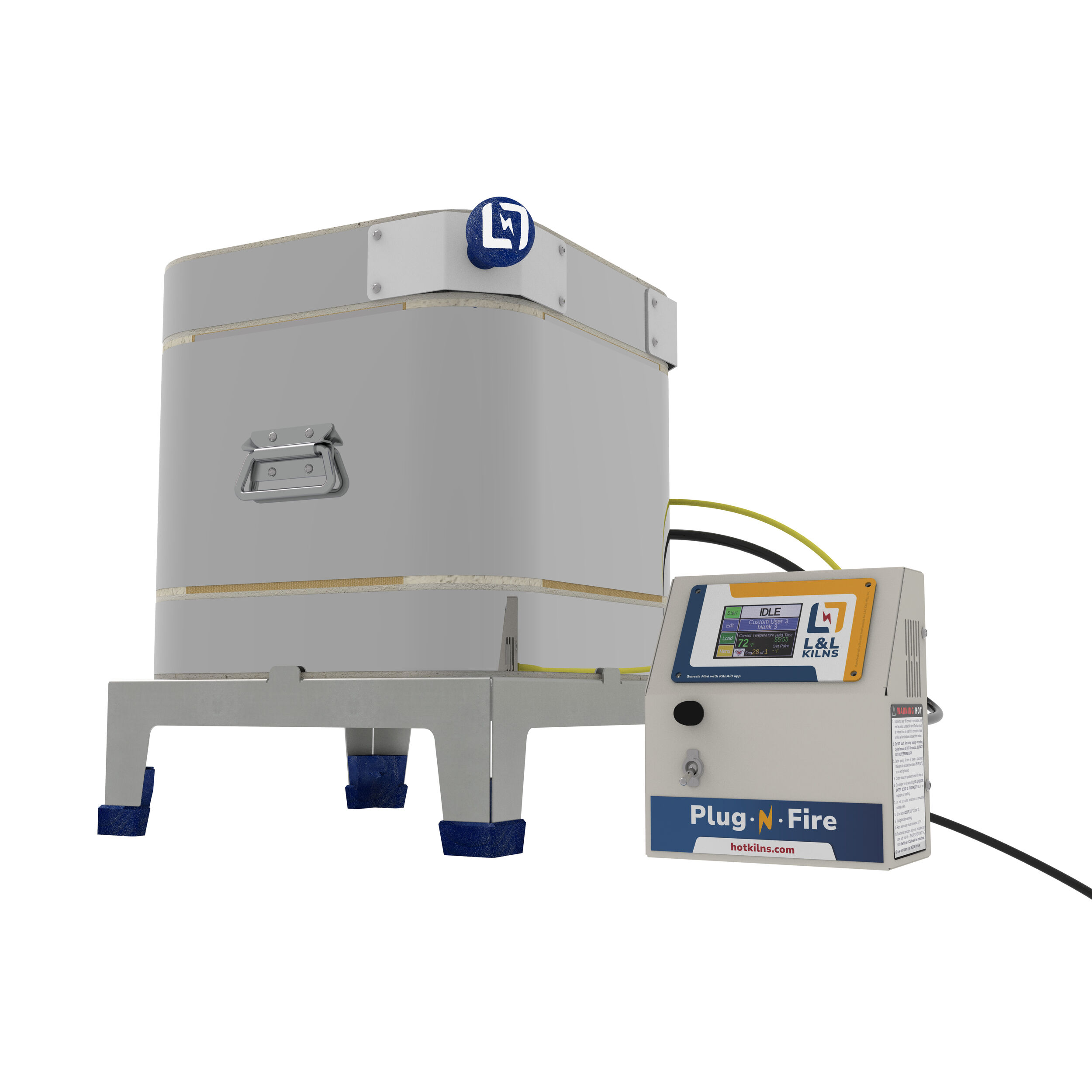
Set Up the Control Panel
- Place the control panel on the right side of your kiln.
Attach the Thermocouples
- Each thermocouple lead wire is numbered to match the thermocouple’s location on the kiln.
- The “#1” lead wire must be attached to the top thermocouple.
- The “#2” lead wire attaches to the bottom thermocouple on a two-section kiln, or the middle thermocouple on a three-section kiln.
- Attach wires by screwing the red wire onto the negative (–) terminal of the thermocouple and the yellow wire onto the positive (+) terminal.
- These terminals are marked on the ceramic block.
- Ensure the thermocouple lead wires do not touch the kiln. Burned wires will cause the control to malfunction.
Plug in the Kiln Sections
- Plug the element box jumper cord labeled “#1” (top section) into the receptacle marked “#1.”
- Make sure the top section’s thermocouple lead wire is also labeled “#1.”
- Repeat for the remaining kiln sections, ensuring the labels match.
Final Steps
- Install the vent (if equipped):
- Attach the vent fan and run exhaust tubing to the outside. See the Vent-Sure Downdraft System Instructions.
- Connect electrical power:
- Refer to the wiring diagram for electrical specifications. All DaVinci kilns are direct-wired.
- Read “Cautions” carefully:
- Review the “OPERATIONS” section before proceeding.
- Vacuum the kiln:
- Make sure the kiln is disconnected from power before vacuuming.
- Perform a test firing:
- Refer to the First Kiln Firing Instructions
Video Instructions
Note: These video instructions are not up-to-date but still helpful.

See https://www.youtube.com/video/dhcUUoYzOa0

See https://www.youtube.com/video/II-hwd9Q1mw