

Kiln Installation Overview
Rev: 2/1/2025
Safety Approvals & Codes
Local Codes
IMPORTANT: Local fire and safety codes override any guidelines provided here. Always consult your local authorities before installing your kiln.
UL499 Listing & UL Standards
- Many (but not all) L&L kilns are listed to UL499 and Canadian standards for the U.S. and Canada by an NRTL (Nationally Recognized Testing Laboratory).
- If your kiln is UL499-listed, it will have a listing mark on its data plate and wiring diagram.
- The Vent-Sure vent system is also listed to UL499 and Canadian Standards for use with L&L kilns in the U.S. and Canada.
- Check here for more details
National Electrical Code (NEC)
- Kiln installations must comply with the NEC.
- Overcurrent protection must be rated at 125% of the kiln’s maximum amperage to accommodate potential surges.
- Consult a qualified electrician or NEC guidelines for specifics.
- See the NEC entry on Wikipedia.
National Fire Protection Association (NFPA)
- NFPA 86 addresses industrial furnaces and ovens; some guidelines may apply to kilns.
- Keep temperatures at combustible floors and ceilings below 160°F (71°C).
- Noncombustible surfaces are strongly recommended.
Uniform Mechanical Code (UMC)
- Section 930.0 of the 2024 UMC discusses small ceramic kiln installations.
- The UMC 2024 Edition states:
- Sides and tops of kilns: At least 18" (457 mm) from noncombustible walls. (Note: L&L recommends 18" but allows for 12" from a non-combustible wall.)
- At least 3' (914 mm) from combustible walls.
- Kilns must be installed on noncombustible flooring at least 2" (51 mm) thick, extending 12" (305 mm) beyond the kiln base.
Clearances & Surfaces
General Dimensions
- Download the General Dimension Drawing for your specific kiln model from our website.
- Review all dimensions, clearance guidelines, and BTU ratings for proper HVAC planning.
Clearances
- Keep at least 12" of clearance from noncombustible walls and materials (18" is recommended) and at least 36" from combustible walls and materials.
- Ensure ample room to open the kiln lid and access control panels, typically 18" to 24" around the kiln.
- Keep surface temperatures near the kiln under 125°F (52°C) to reduce fire risk.
Wall & Floor Materials
- Walls: Choose noncombustible materials like cement board, cinder blocks, or masonry. Consider installing a heat-resistant barrier if closer clearances are necessary.
- Floors: Install kilns on noncombustible surfaces (cement, ceramic tile, stone, slate, masonry) with at least 2" thickness, extending 12" beyond the kiln footprint.
- Never place kilns on wood flooring, carpet, or potentially flammable materials. Even cement floors benefit from the kiln stand for proper air circulation.
Kiln Stand
- Always use the factory-supplied kiln stand to ensure proper airflow beneath the kiln.
- Stands typically raise the kiln about 8" off the floor, reducing heat conduction and fire risk.
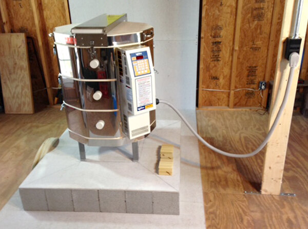
A sound kiln installation with appropriate clearances and materials.
Kiln Room Environment
Location & Protection
- Keep the kiln in a dry, enclosed area protected from weather.
- Provide proper ventilation to reduce corrosive fumes and maintain a dry environment.
- Uninsulated buildings (e.g., garages and sheds) can be acceptable if they remain dry; however, watch for condensation.
- Keep all electrical components dry. If the kiln or wiring becomes wet, thoroughly dry it before use.
Moisture & Corrosion
- Temperature fluctuations can cause condensation (dew) on cold metal surfaces, accelerating corrosion of kiln components and wiring.
- Salt air and humid conditions increase corrosion risks. Consider climate control, dehumidifiers, or improved ventilation.
- Poor ventilation and trapped firing fumes can corrode kiln parts, firebrick, and wiring. Such damage is not covered by warranty.
Ambient Temperature
- Recommended operating range: 0°F to 100°F (–18°C to 38°C).
- Controllers (DynaTrol, Genesis) function best between 32°F and 125°F (0°C to 52°C).
- Below 32°F (0°C), switch the controller to Fahrenheit mode for more accurate readings. The kiln’s own heat helps maintain proper controller operation.
- Prolonged operation above 125°F (52°C) can degrade electronics.
Safety Considerations
- Kiln surfaces can reach 500°F (260°C). Post clear warning signs and use barriers to keep children, pets, and unauthorized individuals at a safe distance.
- Keep a suitable, regularly inspected fire extinguisher (e.g., ABC-rated) nearby.
- Consult local fire codes regarding sprinkler systems, automatic foam extinguishers, or other fire suppression measures.
- If using sprinklers, position them away from direct kiln heat and consider high-temperature-rated or smoke-activated models. Monitor room conditions during peak firing to prevent accidental activation and avoid severe water damage if the building is unattended.
Ventilation
Overview
Proper ventilation is crucial when firing a kiln. Harmful fumes and excess heat can compromise safety and damage equipment. Please refer to our dedicated ventilation page for a complete overview of venting requirements and recommendations.
Room Ventilation
- Adequate room ventilation removes excess heat, reducing fire hazards and preventing controller overheating.
- Use a variable-speed exhaust fan and a thermometer to monitor and adjust airflow.
- Provide approximately 100 CFM of airflow per cubic foot of kiln volume. For example, a 7-cubic-foot kiln needs about 700 CFM.
- An existing HVAC system can help manage excess heat, provided the kiln is properly vented.
- See this link to find out how to calculate room ventilation requirements
Kiln Ventilation
- Proper kiln ventilation removes harmful fumes at the source, ensuring a healthier environment and reducing corrosion.
- Consider a dedicated downdraft kiln vent, such as our VENT-SURE system, to:
- Extract Fumes: Efficiently remove harmful gases from the kiln chamber, venting them outdoors.
- Improve Firing Uniformity: Counteract the natural upward flow of hot air, ensuring more even heat distribution.
- Enhance the Firing Atmosphere: Maintain an oxygen-rich environment, which can improve glaze quality and prolong element life.
Electrical Installation
Before You Begin
- Always hire a licensed electrician. Improper wiring can cause fires, equipment damage, or injury.
- If installing in a public facility (e.g., a school or community center), get approval from the owner or administrator beforehand.
- Select an Installation Location that meets code requirements, minimizes wiring distance, and allows for convenient maintenance.
- Before purchasing a kiln, review its spec sheet to ensure its voltage, amperage, and phase requirements match your building’s supply.
Data Nameplate
- The kiln’s Data Nameplate (usually found on the control panel) also lists voltage, amperage, and phase requirements.
- Review these details with your electrician before installation to confirm proper circuit sizing and component selection.
Voltage
- L&L kilns require a variety of voltages, ranging from 120 V - 480 V. Always match the kiln’s rated voltage to your supply.
- Example: A 208 V kiln on a 240 V supply will overheat, creating a fire hazard; a 240 V kiln on a 208 V supply will be inefficient and may never reach the desired temperature.
- A ±7 volt range is an acceptable tolerance, but larger deviations shorten element life and affect firing capacity.
- Voltage may vary by time of day and location. Use a transformer or change elements to align with your building’s supply if necessary.
Amperage & Circuit Sizing
- The NEC requires circuits to be rated at 125% of the kiln’s maximum amperage.
- To determine circuit size, multiply the kiln’s maximum amperage by 1.25, then select the next standard breaker size.
- Example: A kiln rated at 48 A requires a 60 A breaker (48 × 1.25 = 60). A kiln rated at 60 A requires an 80 A breaker (60 × 1.25 = 75)
- Use a dedicated circuit to avoid overloads and potential fire hazards.
Phase
- Ensure the kiln’s phase (single or three-phase) aligns with your building’s electrical service.
- Residential buildings in the U.S. commonly provide single-phase power, while commercial or institutional settings often have three-phase. Always verify before proceeding.
- Three-phase circuits are balanced on three-section (27" high) kilns. Other heights (such as 18", 22", 36", or 45") are not inherently balanced unless specifically designed for that purpose.
Wiring
- IMPORTANT: Always use copper wire (preferably braided) rated for at least 75°C.
- Never use aluminum wire, which oxidizes under kiln conditions and creates a fire hazard.
- Select wire gauge based on the breaker size and the run length.
Wire Size Chart and Maximum Amp Ratings
In the U.S., a special scale has been developed for the most common wire sizes. This is the American Wire Gauge, or AWG. The following table is based on the 1999 National Electric Code®, Tables 310-16 and 310-18. These are the allowable ampacities of Insulated Conductors, (3) current-carrying conductors in a raceway or cable, and are based on an ambient temperature of 86°F. 105°C values are estimated using 1.15 × the 90°C ampacity.
This is only a starting point. Your electrician must consider the number of conductors in the raceway, ambient temperatures, and the wire run length.
Note: Our recommended wire connection ratings are based on 75°C wire.
| SIZE (AWG/kcmil) | AMPACITY per copper wire temp rating | ||
|---|---|---|---|
| 60°C (140°F) | 75°C (167°F) | 90°C (194°F) | |
| 14 | 20 | 20 | 25 |
| 12 | 25 | 25 | 30 |
| 10 | 30 | 35 | 40 |
| 8 | 40 | 50 | 55 |
| 6 | 55 | 65 | 75 |
| 4 | 70 | 85 | 95 |
| 3 | 85 | 100 | 110 |
| 2 | 95 | 115 | 130 |
| 1 | 110 | 130 | 150 |
| 1/0 | 125 | 150 | 170 |
| 2/0 | 145 | 175 | 195 |
| 3/0 | 165 | 200 | 225 |
| 4/0 | 195 | 230 | 260 |
| 250 | 215 | 255 | 290 |
| 300 | 240 | 285 | 320 |
| 350 | 260 | 310 | 350 |
| 400 | 280 | 335 | 380 |
| 500 | 320 | 380 | 430 |
| 600 | 355 | 420 | 475 |
| 700 | 385 | 460 | 520 |
| 750 | 400 | 475 | 535 |
| 800 | 410 | 490 | 555 |
| 900 | 435 | 520 | 585 |
| 1000 | 455 | 545 | 615 |
| 1250 | 495 | 590 | 665 |
| 1500 | 520 | 625 | 705 |
| 1750 | 545 | 650 | 735 |
| 2000 | 560 | 665 | 750 |
- Locate the kiln within 50' of the breaker.
- Longer distances result in voltage drop and may require an increase in wire gauge. Review this page for more information.
- Route wiring through appropriate conduit and keep it away from the kiln’s hot surfaces to reduce the risk of damage and fire hazards.
Grounding
- Ensure a dedicated ground conductor is installed; never use the ground as a neutral.
- Note: L&L does not use the Neutral at all except for some ancient kilns.
- Proper grounding helps protect against electrical shock and ensures safety devices function correctly.
Fused Disconnect Switch
- Consider installing a fused disconnect switch with a lockout provision near the kiln.
- Provides a reliable means to cut power, preventing unauthorized use and reducing wear on plugs and outlets.
- Ideal for lockout/tagout procedures in industrial or institutional settings, ensuring safe maintenance and inspections.
Plugs & Receptacles (If Applicable)
- For kilns rated at 48 A or less, L&L typically supplies a factory-fitted cord and plug, most commonly a NEMA 6-50P (single-phase) or 15-50P (three-phase). Kilns for markets outside North America do not include a cord.
- Have your electrician install a matching, properly rated receptacle so the cord hangs downward and maintains a secure connection.
- Do not rely solely on unplugging for routine shutoff. A fused disconnect or dedicated breaker switch is safer and more reliable over time.
- Never use an extension cord for a kiln; always plug directly into the receptacle.
Note about Plug and Fuse Ratings:
- L&L Kiln uses a UL499 listed NEMA 6-50P or 15-50P plug and cord that is robustly designed and marked for 50 amperes at up to 250 Volts AC, 1 Phase (or 3 phase for the 15-50P), with a grounding prong. The (2 or 3) current carrying conductors are 6 AWG, which according to the 2002 NEC (National Electrical Code) Table 400.5 for flexible cables have an allowable ampacity of 55 amperes, and the grounding conductor is 8 AWG, which does not usually carry any current. The plug, or cap, is designed and constructed so there are no exposed current-carrying parts except for the prongs, which only carry current when the plug or cap is safely inserted into its mating receptacle.
- This plug and cord set is listed for carrying 50 amperes at the proper voltage and phase. All L&L kilns that use these plugs and cords are also listed as complete appliances, with the ratings listed in L&L Kiln Mfg., Inc. catalogs. When installed, the circuit that supplies power to the kiln must be designed per NEC requirements, and in many cases must be provided with conductors and overcurrent protection rated for 60 amperes, or 125% of the ampere listing of the kiln. (E.g., the E23T is listed at 48 amperes. 48 * 1.25 = 60 ampere rating for overcurrent protection and power supply conductor rating.) This may initially create some confusion, but remember that the kiln is UL listed with the NEMA 6-50P plug and cord set as a component of the appliance - it is the power supply circuit that must be protected at 125% of the listed rating, not the individual components inside the appliance.
Hardwired Installations
- Kilns rated above 48 Amps must be hardwired directly to a fused disconnect or breaker panel.
- Use flexible conduit to run wiring from the panel to the kiln’s control box, then connect the conductors to the internal power connection block.
- Because of the many possible installation variations, L&L does not provide materials or cables for hardwiring.
- For kilns drawing 48 Amps or less, hardwiring is optional and may be preferred for added security.
- If performed correctly, hardwiring does not void the warranty. Consult a licensed electrician and follow all applicable codes and guidelines.
- If you are hardwiring the kiln, the wire that connects to the kiln's terminal block should be rated for 105°C
Final Checks & Initial Testing
- Verify that all connections are secure and properly tightened.
- Ensure no wires, cords, or plugs touch the kiln's exterior.
- Confirm the kiln is properly grounded and that safety devices (such as fused disconnects or circuit breakers) function correctly.
- Briefly power the circuit (with the kiln off) to confirm the breaker holds and check for any unusual odors or sounds.
- If anything appears incorrect or unsafe, shut down power immediately and consult your electrician before proceeding.
Kiln Assembly
Once you thoroughly read this overview and have made the appropriate preparations, you can move on to assembling your kiln.
The exact assembly instructions will vary depending on the model of your kiln. find the assembly directions for your specific kiln under the assembly section of our website
Kiln Adjustments & Maintenance
Leveling the Kiln:
- Level the kiln during installation. (Suggestion: use a level)
- Use thin metal shims under the legs (never use wood or combustible materials).
- Some kilns have leveling bolts or pads.
- Ensure the base does not wobble.
Adjust the Hinge Properly:
- Refer to the assembly instructions for your specific kiln in the Support Menu.
- Adjust the hinge to allow for expansion caused by heating.
- L&L includes expansion slots in the hinges (applies to top-loading kilns only).
Thermocouples:
- Insert thermocouples at least 1” (2.5 cm) from the inside surface of the kiln.
- Ensure the thermocouple tip protrudes into the kiln to avoid measuring lower temperatures, which could cause the kiln to fire hotter than the proper temperature.
- Replace thermocouples when they are no longer accurate (Type K thermocouples last about as long as kiln elements, so replace thermocouples when you replace elements).
- When reassembling the kiln, carefully observe thermocouple polarity and zone placement. See hotkilns.com/tc-polarity.
Safety and Emergency Procedures
Operational & Maintenance Safety
- Never leave the kiln unattended during critical firing stages.
- Wear PPE like heat-resistant gloves and eye protection when loading and unloading.
- Keep flammable materials away.
- Regularly inspect elements, wiring, and firebrick for damage.
- Clean the kiln to remove dust and debris.
Emergency Procedures
- Have a clear plan for kiln-related emergencies (fire, electrical issues).
- Ensure all users know how to safely shut down the kiln in an emergency.