General Assembly Instructions
Rev: 2/1/2025
GETTING STARTED
ASSEMBLY INSTRUCTIONS FOR THESE KILNS
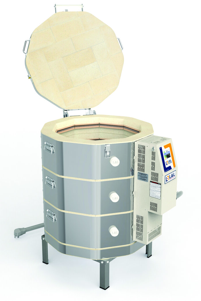
Easy-Fire
School-Master
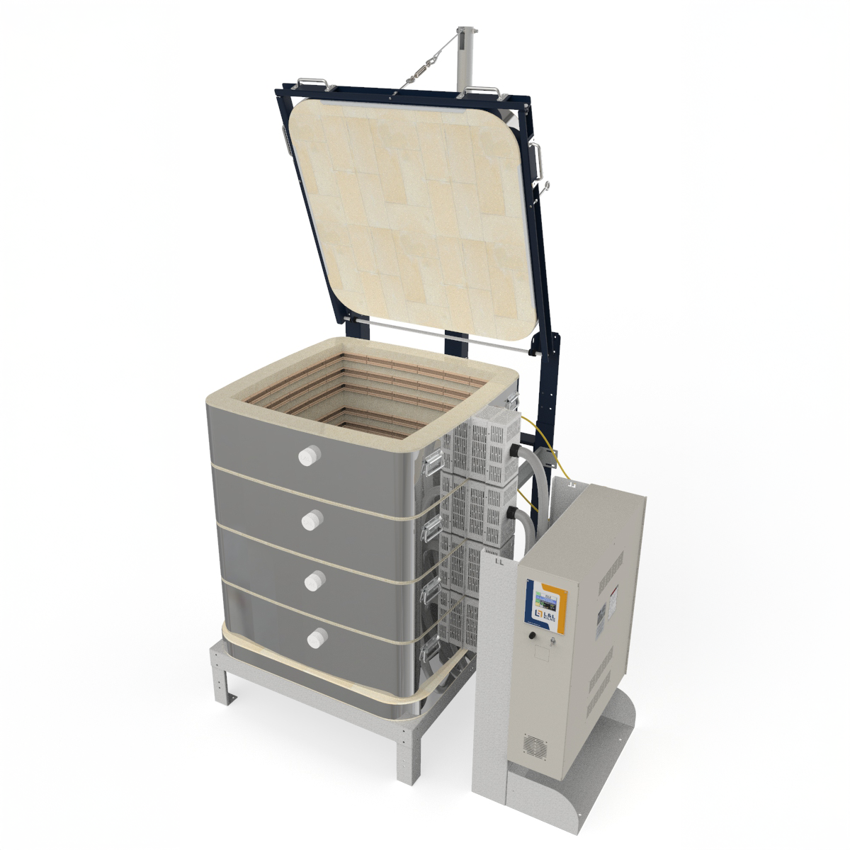
eQuad-Pro
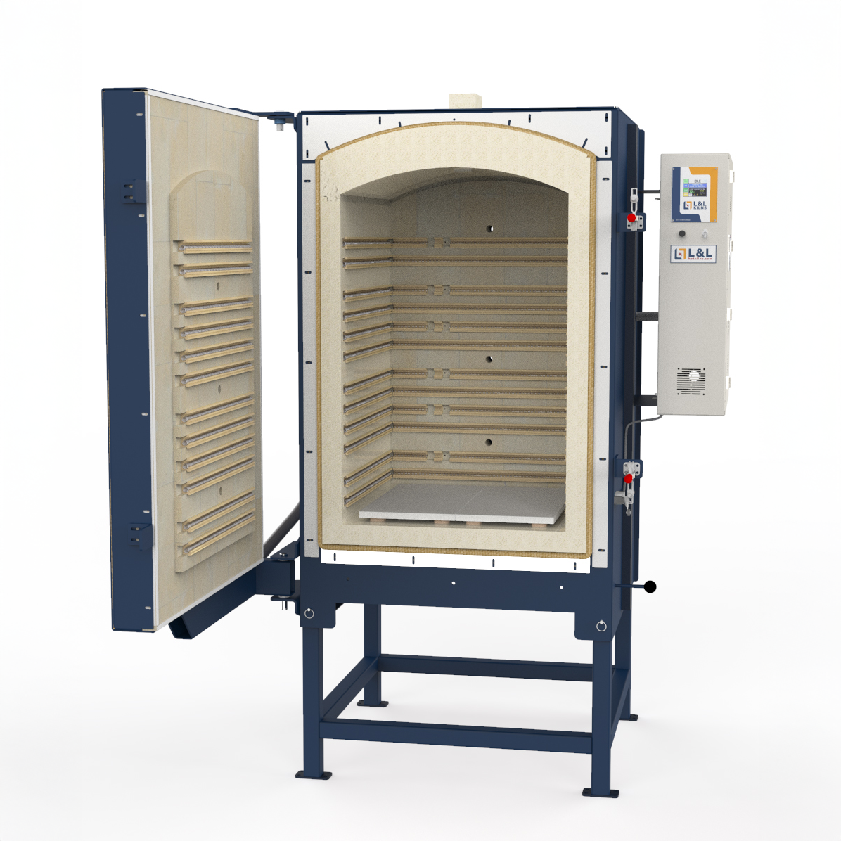
Jupiter
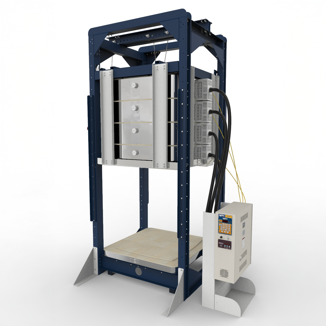
JH Crystalline
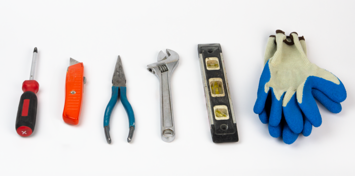
TOOLS NEEDED FOR THE JOB
You will need the following tools for the job:
- Phillips-head screwdriver (medium size head)
- Knife
- Needle-nose pliers
- Adjustable Wrench
- Level
- Safety Gloves
installation
Before assembling your kiln, review our Preparation & Installation page for codes, clearances, ventilation, and electrical installation information.
video instructions

See https://www.youtube.com/video/f7LriKDJ4mE?si=FYQiRMoeDmgEhnbJ
This video will guide you through the unpacking and assembly of our most popular Easy-Fire kiln, the e23T-3. While slight variations between different models exist, these instructions should mostly apply to all Easy-Fire, School Master, and Equad-Pro kilns. The e23S-JH Crystalline Kiln will also use these instructions.
UNPACKING
Inspect your kiln
UNPACKING
SHIPPING DAMAGE AND INSPECTION
- FREIGHT COMPANIES ALLOW 2 DAYS TO REPORT SHIPPING DAMAGE. WE CAN NOT HELP YOU WITH A DAMAGE CLAIM AFTER 2 DAYS.
- If the box is dented, crushed, unbanded, or off the skid, note it on the Delivery Receipt. Check the number of cartons against the Delivery Receipt. Inspect the contents while the driver is present. If this is not possible, take photos and mark the Delivery Receipt “SUBJECT TO INSPECTION.” If obvious severe damage is visible, take photos and refuse the shipment.
- IF YOU FIND DAMAGE: Take as many photographs of everything as soon as you can and email them to service@hotkilns.com. The time stamp on these pictures/emails is critical when filing a damage claim! If you can, write a description of the breakage, damage, or shortage on all copies of the freight bill before you sign it. Make your notations as specific as possible to protect if concealed damage is subsequently discovered. (Sometimes, the shipper may not allow you to do that).
- See hotkilns.com/shipping for full policy.
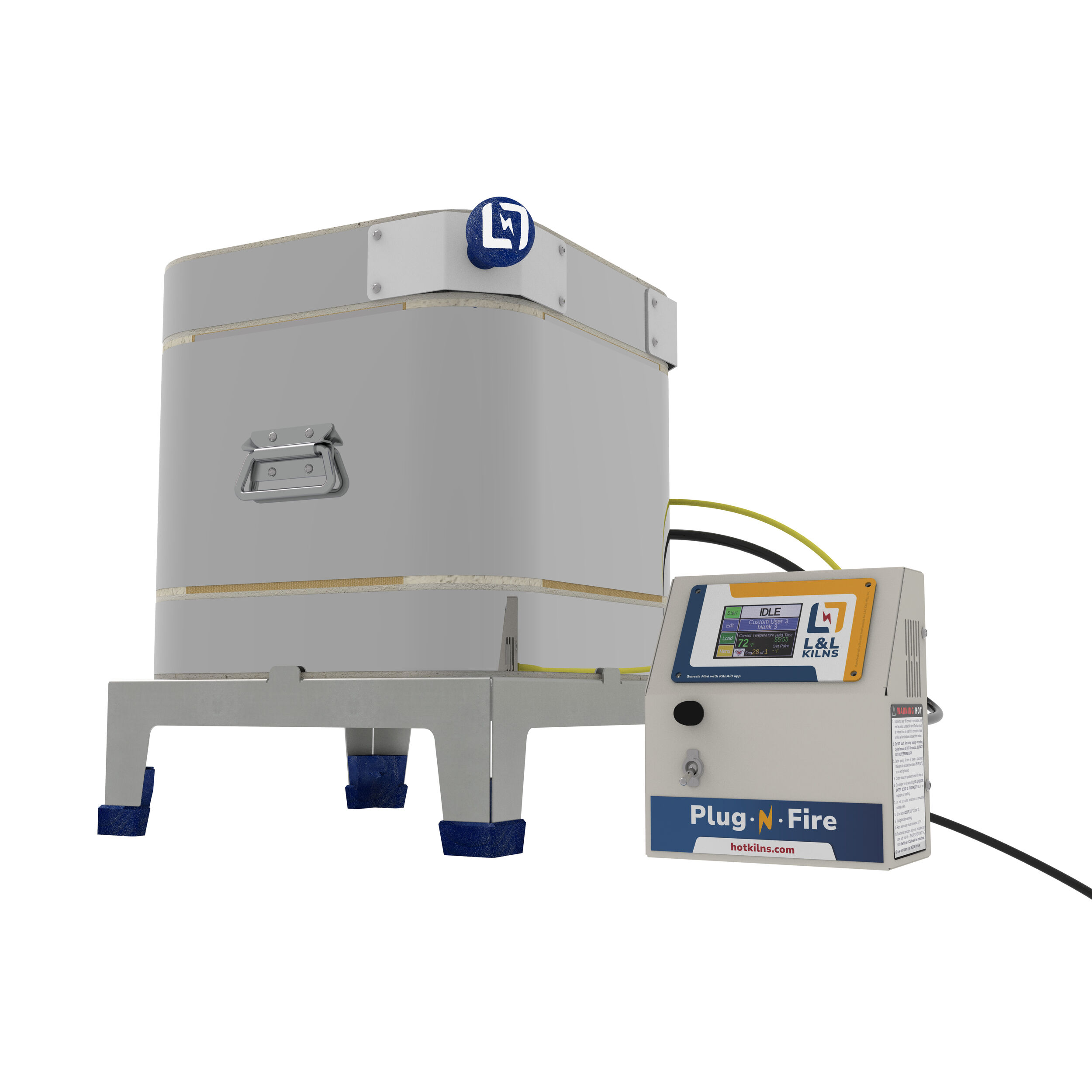
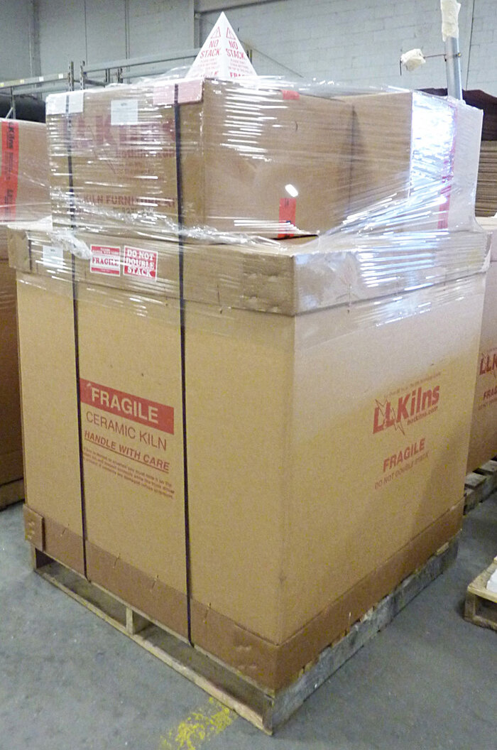
Below is a picture of how your kiln should arrive: (Note that the below picture shows a kiln as ordered with a furniture kit and vent)
Unpack Instructions, Vent, and Furniture Kit
1) Remove the two separate Furniture Kit and Vent-Sure vent system boxes, if ordered, from the top of the kiln carton. Sometimes, these may be packed in individual boxes inside the main carton.
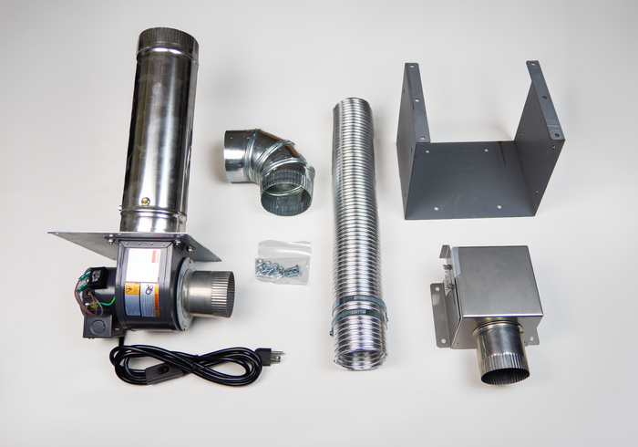
2) If you ordered a Vent-Sure vent system you will find the following items inside the cardboard box:
- Flexible ductwork
- Bypass collection box
- Galvanized 90-degree elbow
- Vent motor with mounting bracket and duct attached for venting through a wall.
- Multi-mount bracket
4) If you ordered a Rolling Stand, see this.
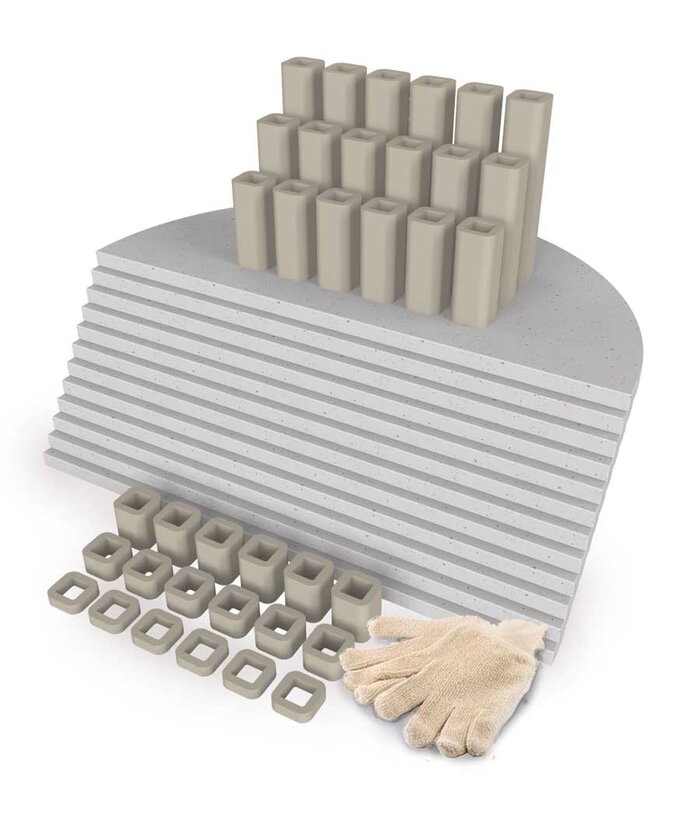
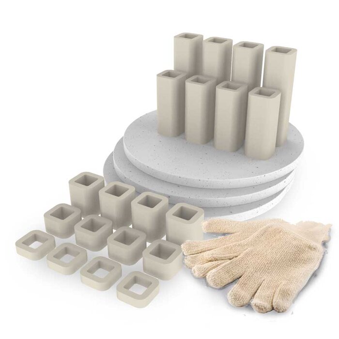
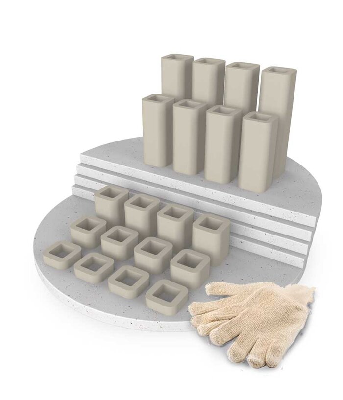
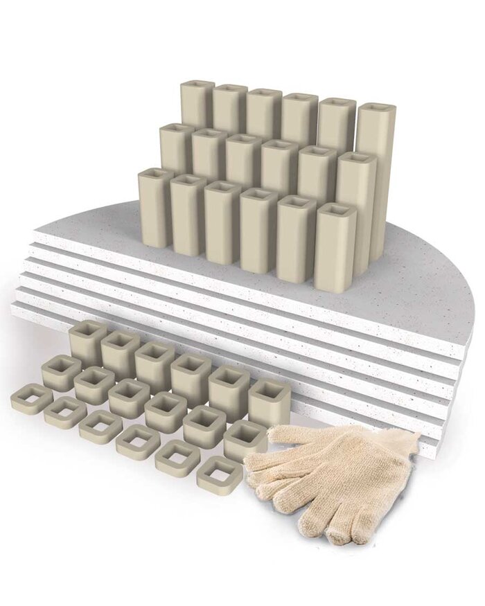
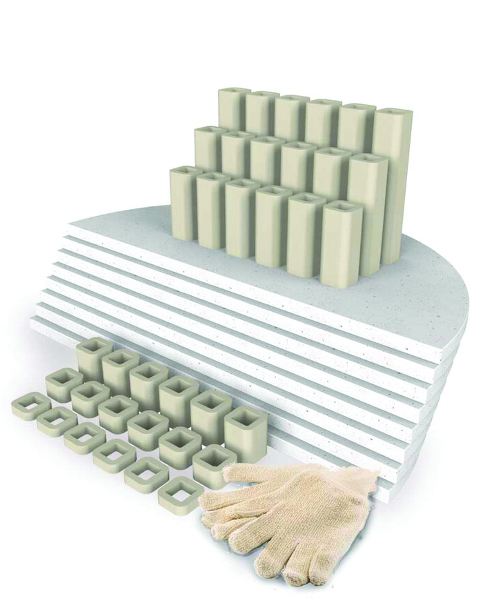
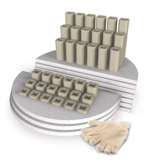
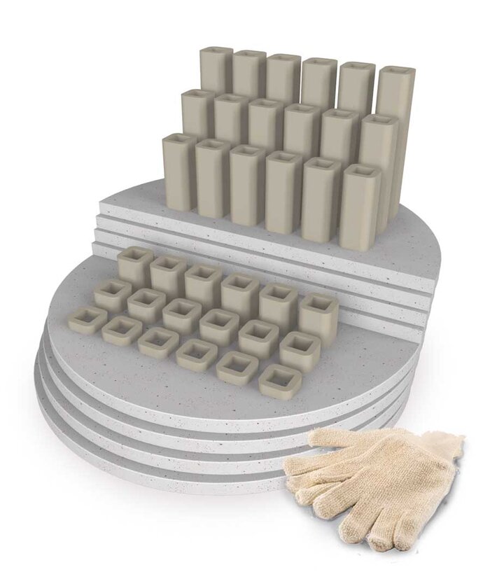
3) If you ordered the standard Furniture/Accessory kit you will find the following:
e14S-3:
- Three 12'' full round shelves
- Four each 1/2'', 1'', 2'', 4'', and 6'' square posts
- A pair of temperature-resistant gloves
e18S-3 or e18M-3:
- One 15'' full round shelves and four 15'' half shelves or six 15'' half shelves
- Four each 1/2'', 1'', 2'', 4'', and 6'' square posts
- A pair of temperature-resistant gloves
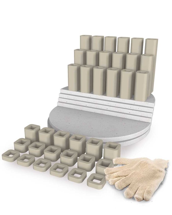
For an e18T-3:
- Two 15'' full round shelves and four 15'' half shelves or eight 15" half shelves
- Six each 1/2'', 1'', 2'', 4'', 6'' and 8'' square posts
- A pair of temperature-resistant gloves
For an e23S-3 or an e23M-3:
- Six 20'' round half shelves
- Six each 1/2'', 1'', 2'', 4'', 6'' and 8'' square posts
- A pair of temperature-resistant gloves
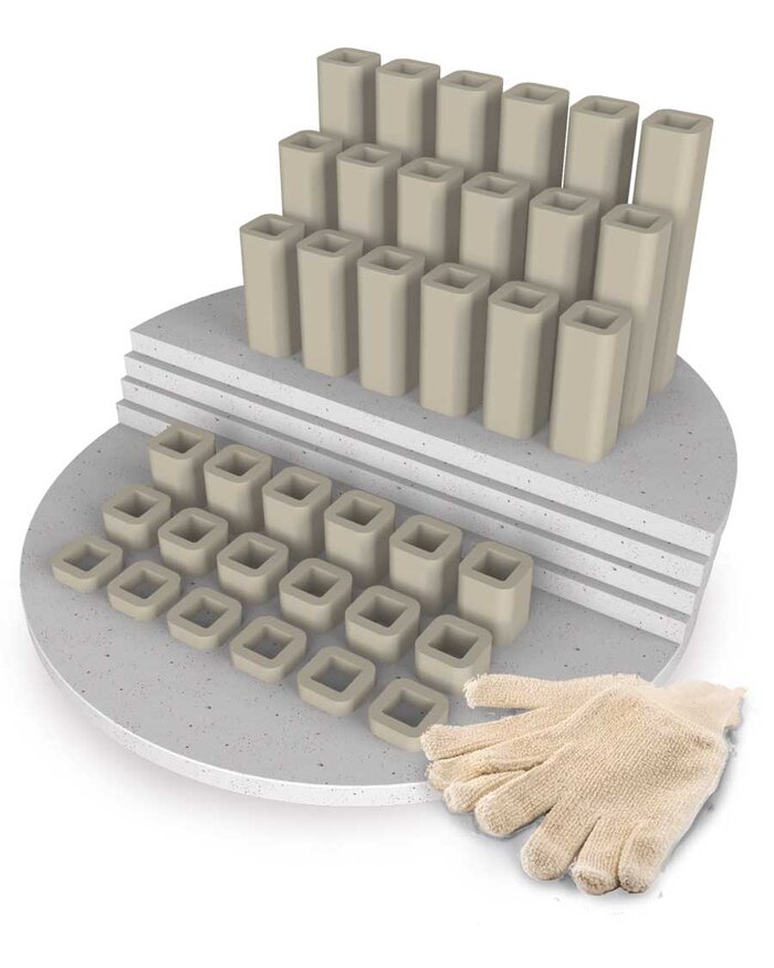
For an e23T-3, e23M-3, SM23T-3, JD230-3, JD230-JH, or eQ2327-3:
- Eight 20'' round half shelves
- Six each 1/2'', 1'', 2'', 4'', 6'' and 8'' square posts
- A pair of temperature-resistant gloves
For an e28S-3 or e28M-3:
- Six 25-1/2'' half shelves
- Six each 1/2'', 1'', 2'', 4'', 6'' and 8'' square posts
- A pair of temperature-resistant gloves
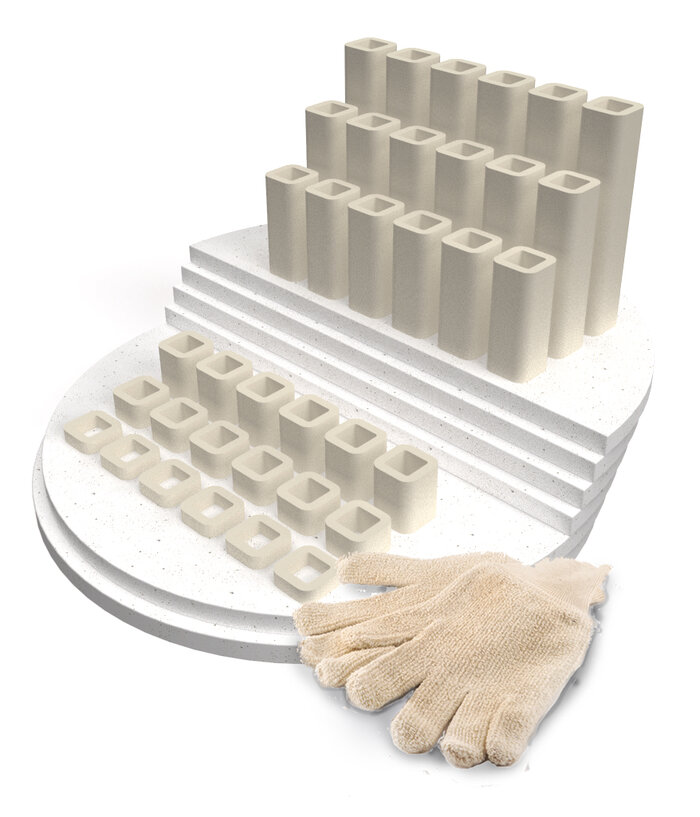
For an e28T-3, JD2927-3, JD2927-JH, or eQ2827-3:
- Eight 25-1/2'' half shelves
- Six each 1/2'', 1'', 2'', 4'', 6'' and 8'' square posts
- A pair of temperature-resistant gloves
For an eQ2836-3 or JD2936-3:
- Ten 25-1/2'' half shelves
- Six each 1/2'', 1'', 2'', 4'', 6'' and 8'' square posts
- A pair of temperature-resistant gloves

For a JD2945-3:
- Twelve 25-1/2'' half shelves
- Six each 1/2'', 1'', 2'', 4'', 6'' and 8'' square posts
- A pair of temperature-resistant gloves
Where to find the boxes
- All Easy-Fire, School-Master, and eQuad-Pro kilns use a foam mold on top of the body that also holds the kiln base slab.
- e14S-3, e18S-3, e18M-3, e18T-3, e23S-3, e23M-3, and e23T-3 kilns are packed with the stand and instruction manual in a separate box beside the kiln body and shrink-wrapped to the kiln body.
- e28S-3, e28M-3 and e28T-3 kilns have the stand and instruction manual packed in a separate box and placed on top of the kiln base encased in a foam mold.
- M&T models are packed with the furniture kit, vent, and rolling stand (if ordered) on top of the exterior packaging. It is then all strapped and shrink-wrapped to prevent separation while in transit.
- S models usually have the furniture kit (if ordered) packed on top of the foam mold.
- Vent Controls are packed inside the sleeve with the kiln.
- Vents, vent doublers and additional small parts are packed on top of exterior packing and shrink-wrapped and strapped.
Remove Top from Carton
- Remove the packing slip from the packing list enclosed envelope.
- Cut the banding around the kiln box.
- With a screw driver pry off the staples holding the top of the box to the box sleeve and remove the top.
Unpacking the kiln
- With a screw driver pry off the staples holding the bottom box tray to the box sleeve.
- Next, remove the cardboard inset from the carton, and remove the carton sleeve from the skid.
- The heavy-duty kiln stand containing a white box, or manila envelope, with the stand legs positioned around it will be set on top of the kiln. This will be slightly covered by the foam packaging tubes.
- Push the foam tubes away from the kiln body. If desired, these can be completely removed by using a knife to carefully cut the plastic tubing by the base of the kiln. There should be little to no foam there. Be careful not to scratch the kiln with your knife.
- Carefully cut off the stretch wrap that is around the kiln. Be careful not to scratch the kiln with your knife.
- Remove the kiln stand base from the top of the kiln. The kiln manual, in a white cardboard box or manila envelope, surrounded by the four kiln stand legs should be resting within the edges of the kiln stand base.
- If you ordered an e18S-3, e18T-3, e23M-3, e23T-3, or e28T-3, or a SM23T-3 or SM28T-3, your kiln floor will be on top.
- If you ordered an e23S or e28S the floor of the kiln will not be on the top, it will be on the bottom of the kiln as it helps secure the spring hinge bracket which is assembled for shipping.
- Notice that the spring on your spring hinge IS engaged and in working condition.
If you need to move the kiln section by section
See this page for weights and dimensions of the kilns.
ASSEMBLING THE KILN
 ASSEMBLING THE STAND
Next, using the enclosed stand hardware, assemble the kiln stand. If ordered, also use the vent system components and hardware to finish the assembly of the kiln stand.
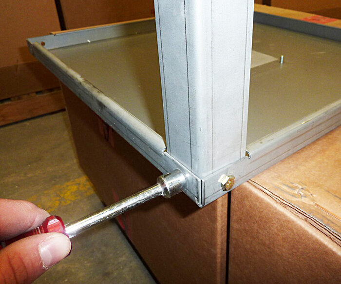
- Assemble the stand legs. Make sure all the stand legs are tight. Use a nut driver or an adjustable wrench to do this.
- NOTE: If you did not order a vent then your stand is completely assembled after this step.
Each leg gets bolted to the stand with two
1/4-20 bolts provided. They do not need nuts.

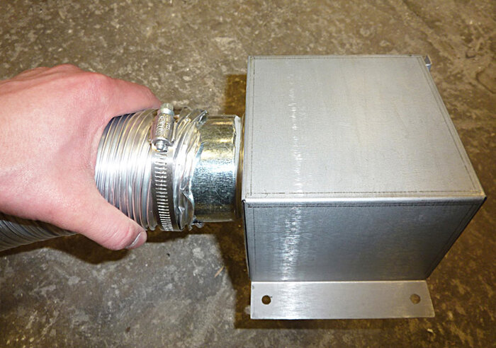
Attach the flexible vent tube to the outlet of the vent collection box. It takes some patience to get the flexible tube around the fitting. Tighten the Breeze clamp to secure the duct to the outlet.
Installing the flexible duct onto the bypass collection box of the vent-sure vent system.

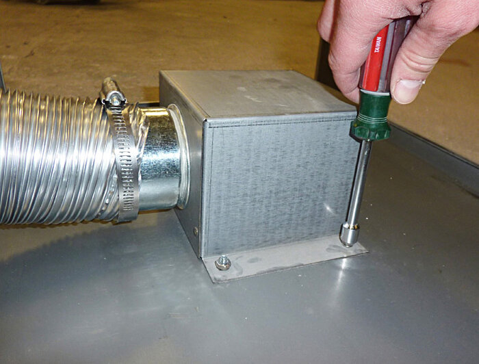
Attach the bypass collection box using the studs that are secured to the bottom of the stand and the supplied mounting hardware, four 10-24 nuts, and lock washers.
The bypass collection box fits over four studs on the bottom of the stand. The lock washers are used between the bypass box flanges and the nuts.
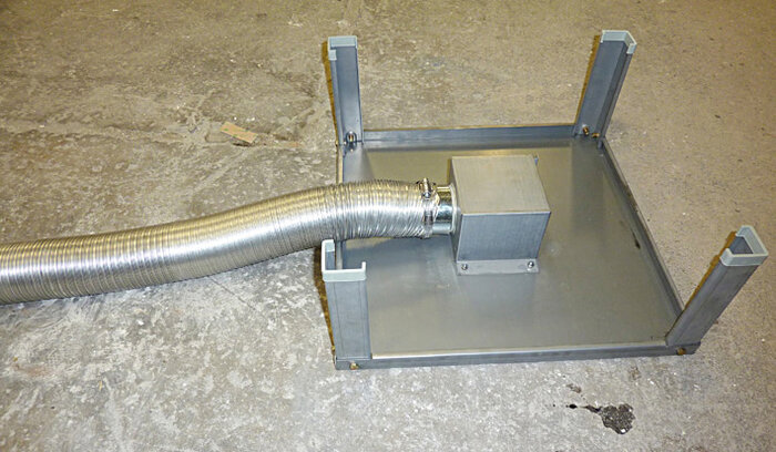
The fully assembled stand.
 DISENGAGING THE SPRING-HINGE AND REMOVING THE LID
- The next step is to remove the lid from the kiln which can only be done once the spring hinge has been disengaged.
The hinge is shipped assembled (with the spring engaged). This way you can see how it all goes back together. WARNING: Spring tension MUST be released before disassembling the lid. SERIOUS INJURY COULD RESULT IF NOT DONE PROPERLY.


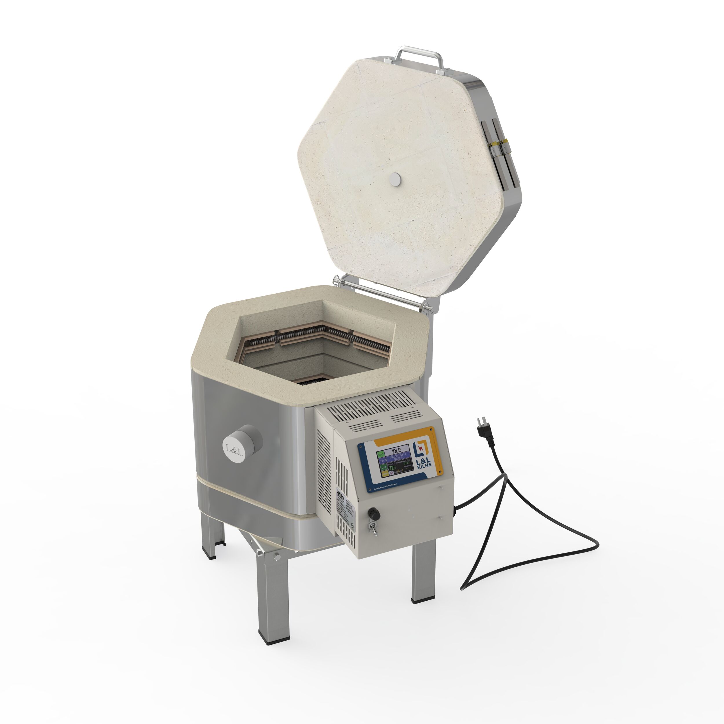
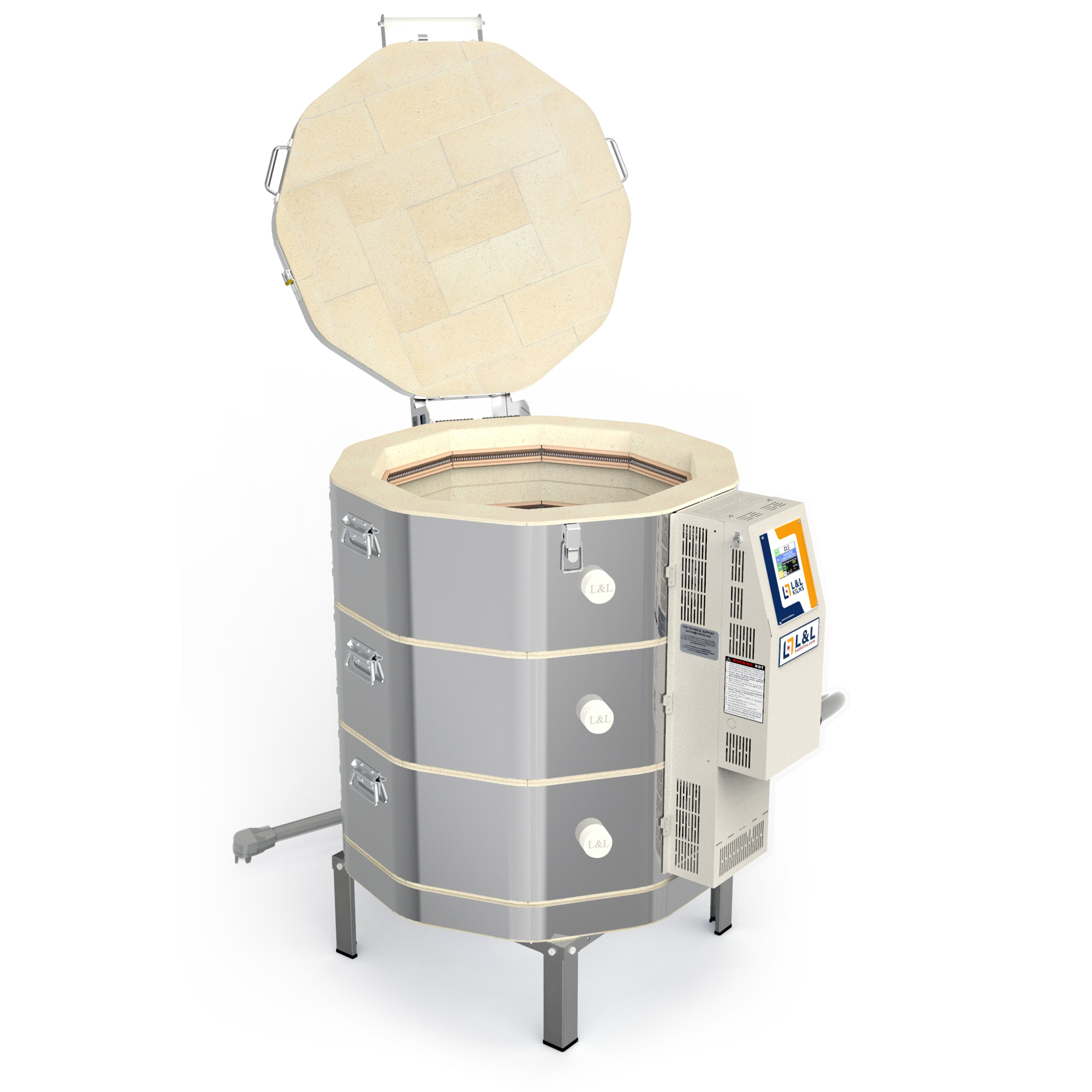
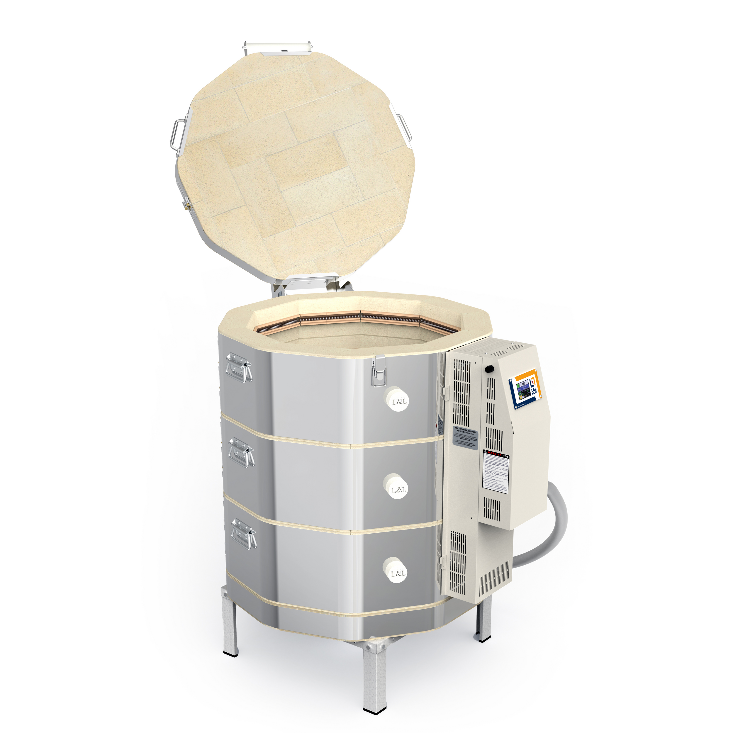
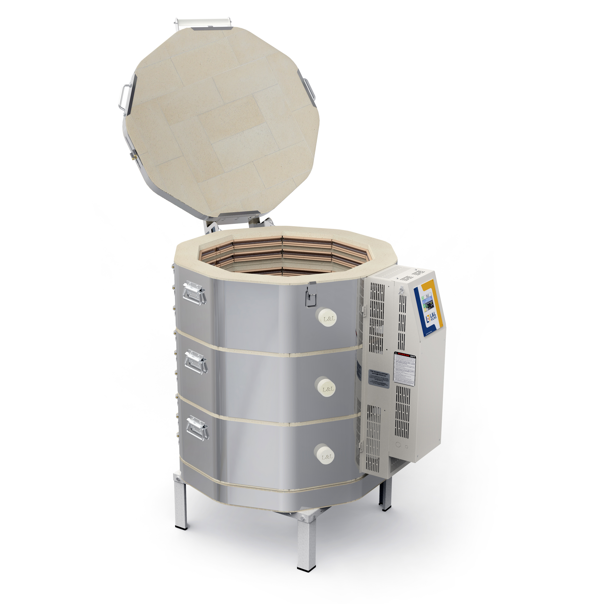
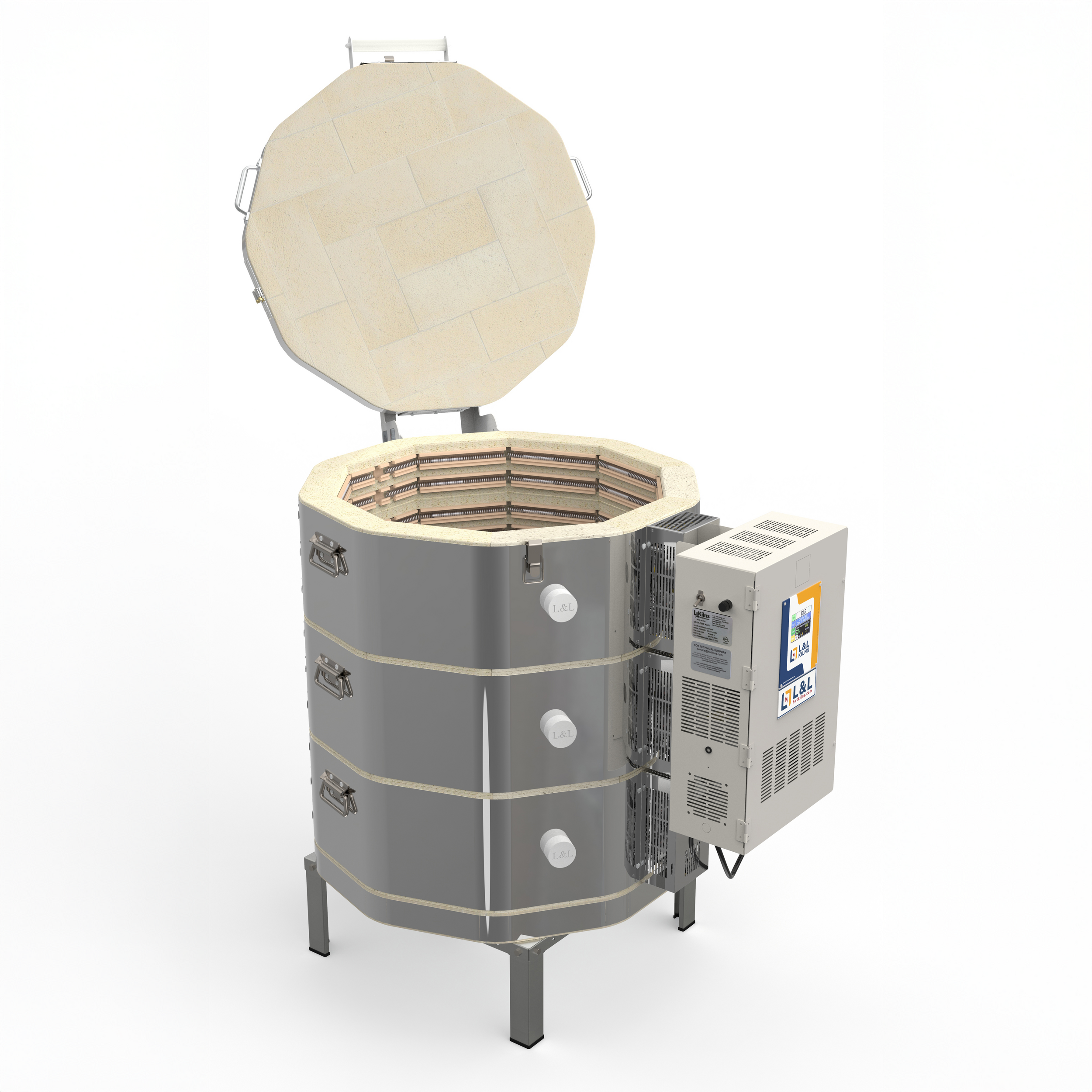
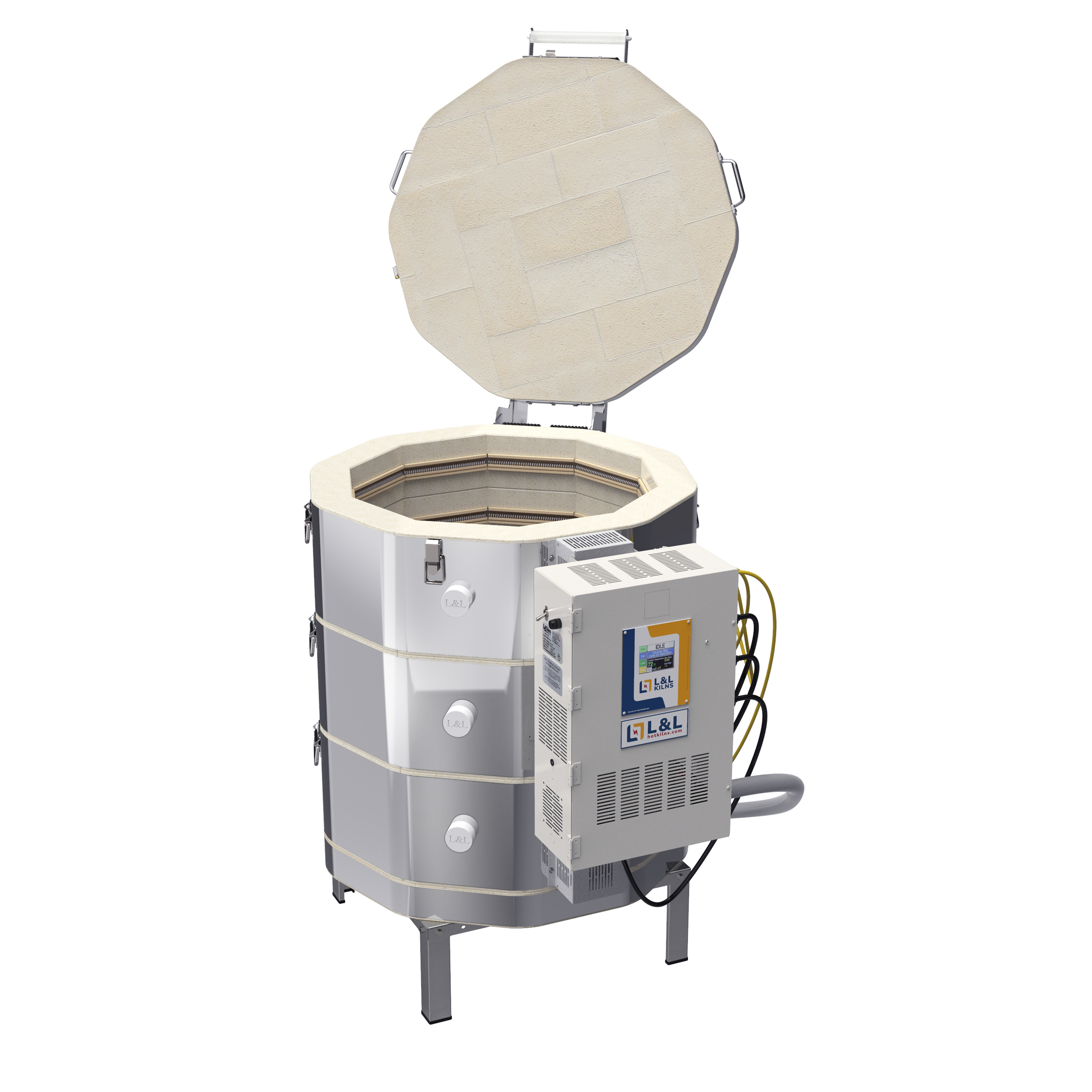
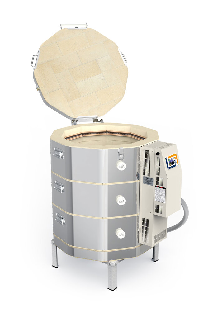
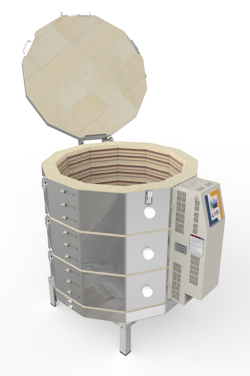
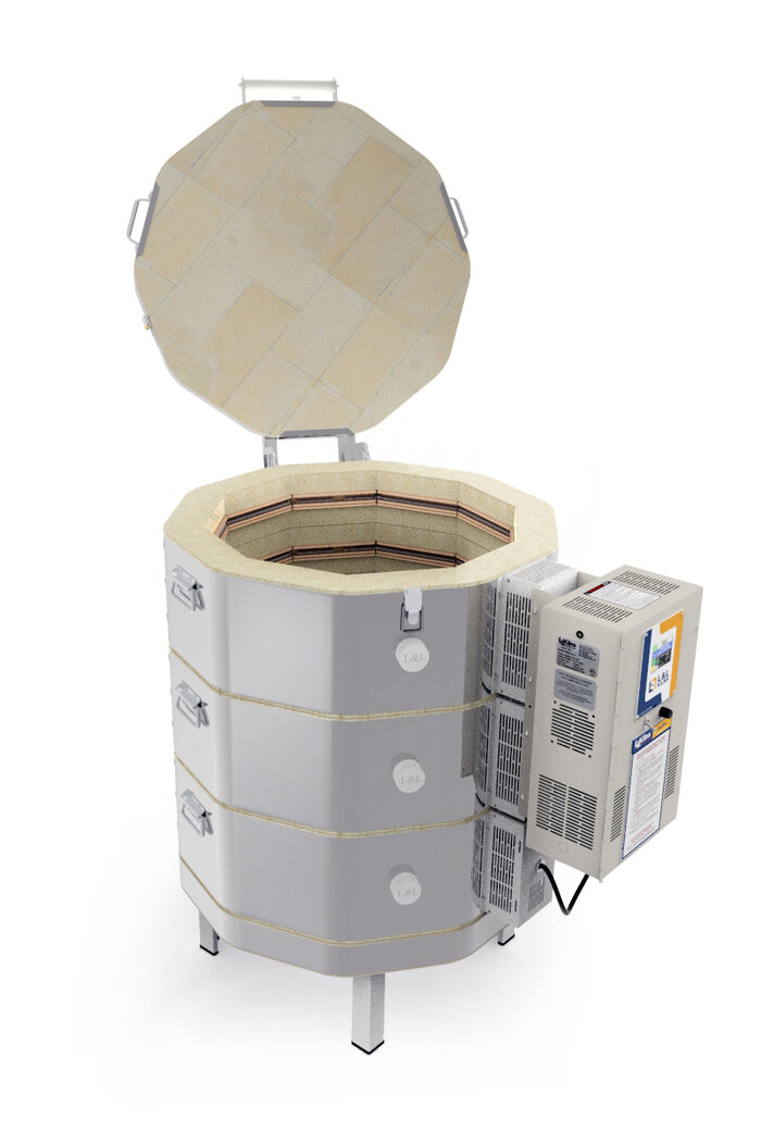
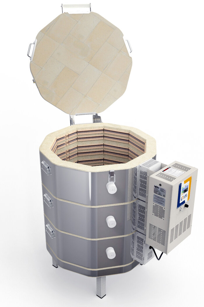
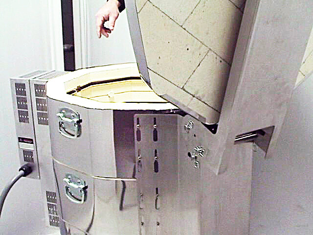
Unclasp the latch underneath the lid handle and open the kiln lid to its fullest extent.
The kiln with the lid opened. THIS IS HOW THE SPRING TENSION IS RELIEVED BEFORE REMOVING THE SPRING. WARNING: THIS IS A CRITICAL STEP!

- Remove one of the cotter pins from the top-most hinge bar that only goes through the lid bracket.
Removing a cotter pin from the top-most bar.

Slide out the top-most hinge bar, set this aside with the cotter pin that you already removed.
Removing the top-most bar.


Carefully close the lid of the kiln. NOTE: By removing the top-most hinge bar the springs have been disengaged and the full weight of the lid will now exert its downward force. Use caution when performing this step.
The closed lid without the top-most hinge bar.

Remove one of the cotter pins from the middle hinge bar. This is the one that runs through the springs.
Removing a cotter pin from the middle bar.

Grasp both of the springs with one hand and carefully slide out the middle hinge bar. The springs will be freed once the bar has been removed. Set this all aside, along with the cotter pin that you already removed.
Removing the middle bar and springs.

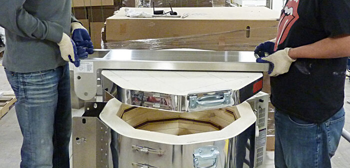
- Your lid is now free of the kiln rings and can carefully be removed.
Lifting the lid off of the kiln body.

REMOVING THE HINGE
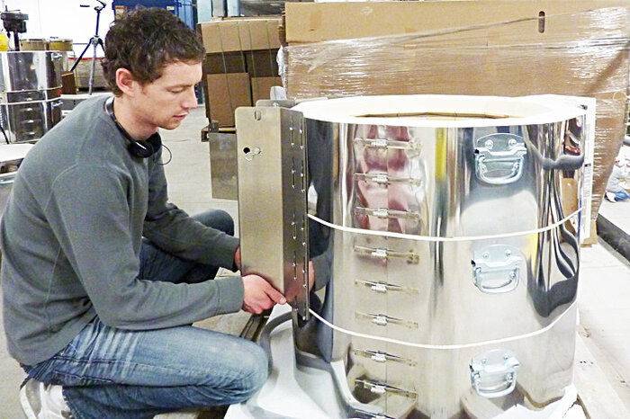
- Loosen the screws of the large hinge piece that holds the three rings together (or the two rings and bottom).
Gently pull the ring hinge piece up and away from the kiln.
Pulling the hinge piece up and away from the kiln. It should slide up easily. If not check all the screws because it only takes one screw that is not loose enough to prevent the hinge piece from sliding up.
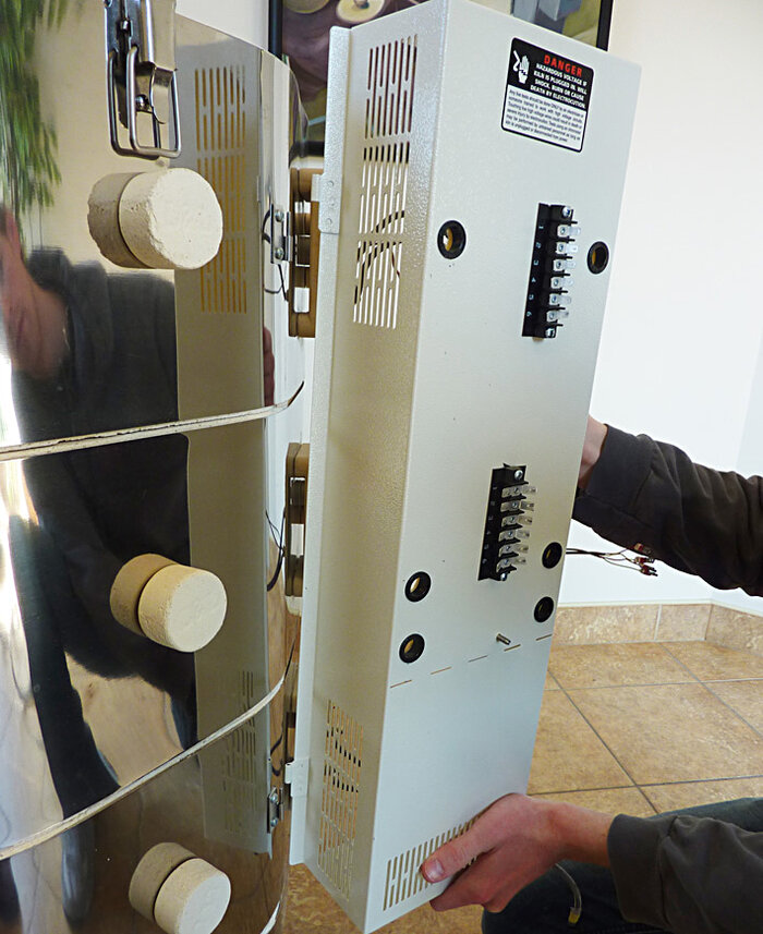
REMOVING THE CONTROL PANEL AND ELEMENT COVER AS ONE ASSEMBLY
You have two choices. You can remove the Control Box and Element Cover Box as ONE assembly or you can first remove the Control Box from the Element Cover Box and then remove the Element Cover Box. The easiest method, in our opinion, is to remove the whole assembly. However, both methods are given.
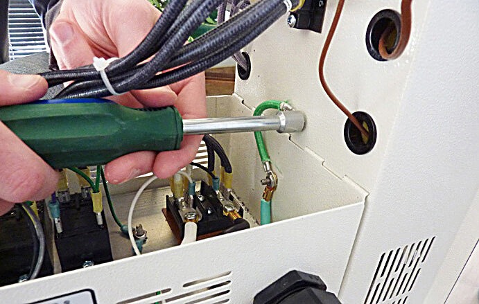
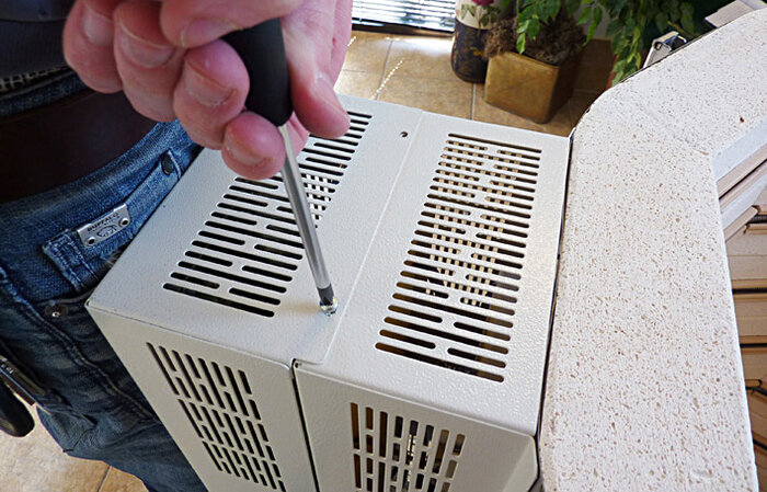
- Remove the two screws that hold the outer portion of the control panel to the element terminal box and set these aside.
Removing the two screws that hold the control box closed.
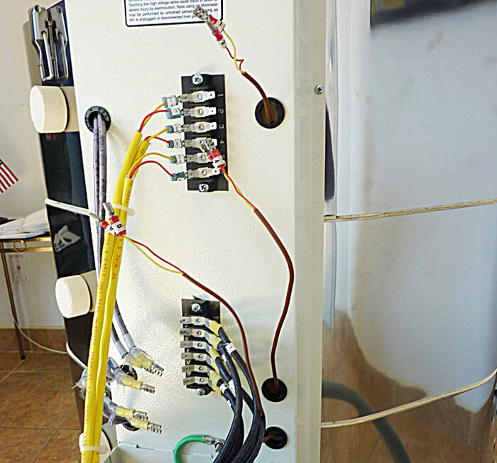
- Hinge the DynaTrol portion of the control panel down exposing the wire connection terminals.
The control box hinged down.
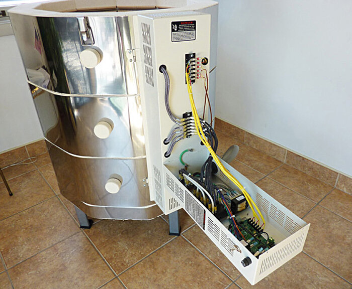
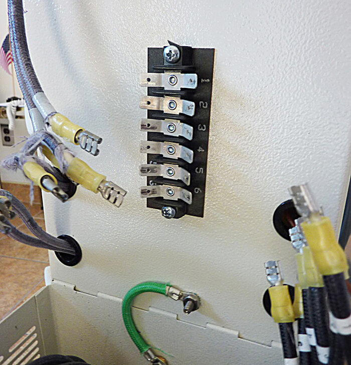
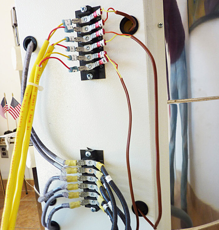
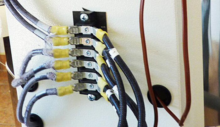
- Remove the wires numbered 1 through 6 from the left side of the Power Terminal Strip and the right side of Thermocouple Terminal Strip.
Wires are shown disconnected.
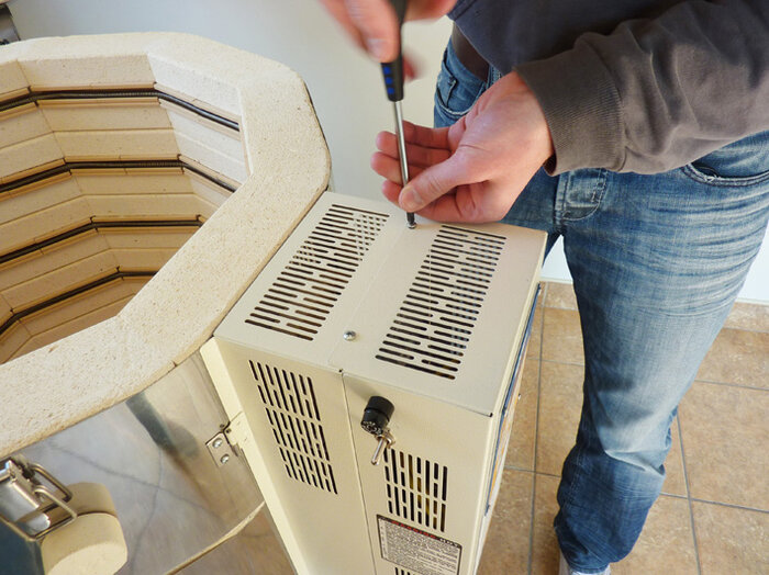
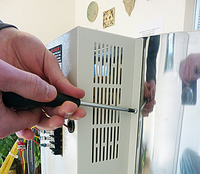
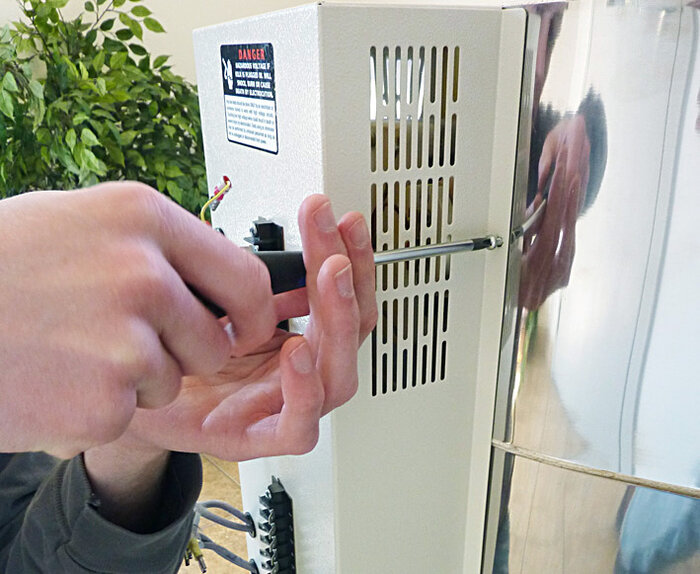
- Remove the two screws that hold the Element Cover Box to the kiln. These are on the right side of the Cover Box. Set these aside.
Removing the two screws that hold the element cover box closed.

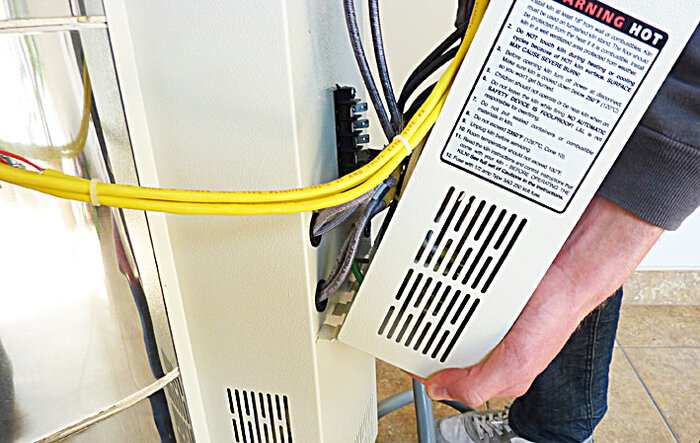
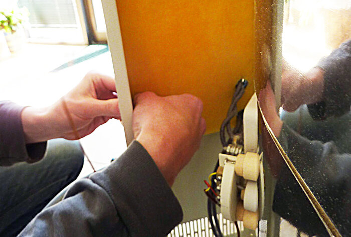
- Swing the whole assembly away from the kiln body, to the left, carefully feeding the element and thermocouple wires through their respective holes
Swinging the whole assembly to the left and removing the wires.
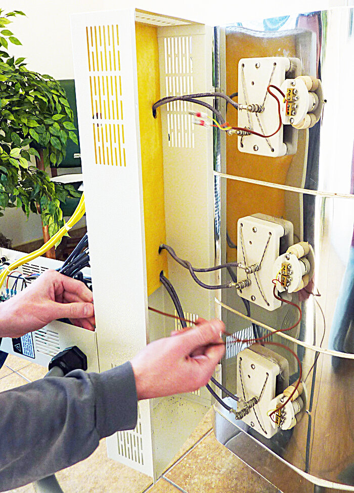
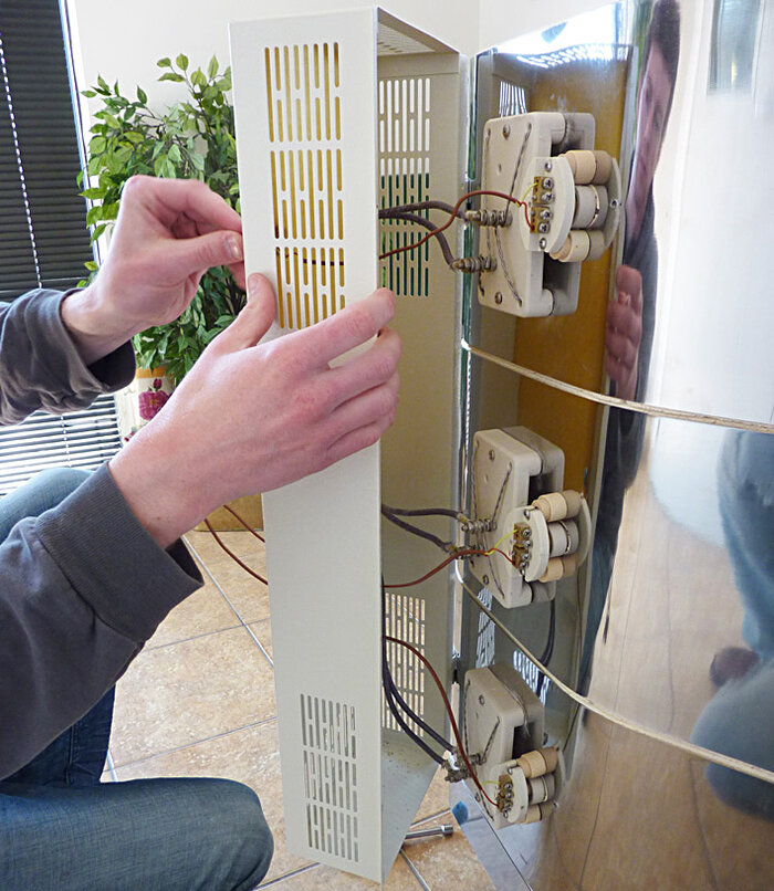
- Gently lift the whole assembly off of the hinges on the left of the Element Cover Box.
Lifting the whole assembly off of the kiln body.
- Now skip to the section called “LOCATING THE KILN”.
REMOVING THE CONTROL BOX
This is method number two.
Remove the two screws, that hold the outer portion of the control panel to the element terminal box.
Removing the two screws that hold the control box closed.
Hinge the DynaTrol portion of the control panel down exposing the wire connection terminals.
The control box hinged down.
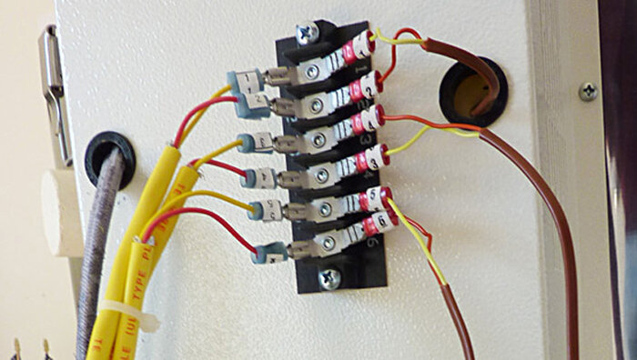
- Remove the wires numbered 1 through 6 from both sides of the Thermocouple Terminal Strip.
Disconnecting the thermocouple wires.
- Remove wires numbers 1 through 6 from both sides of the Power Terminal Strip.
Disconnecting the power wires.
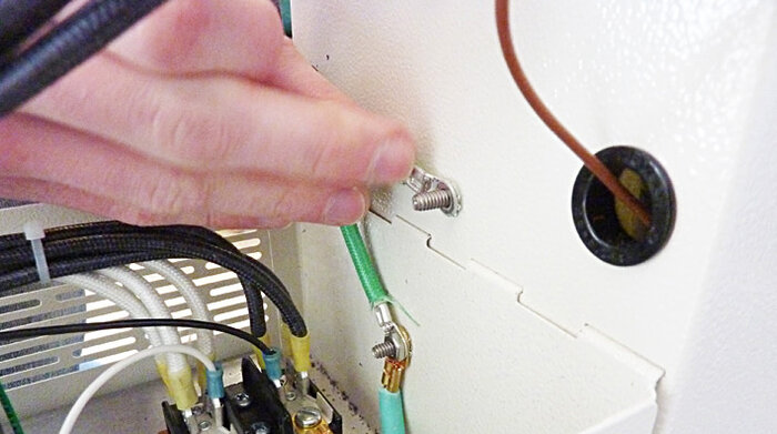
- Remove the green ground that connects the front panel to the rear panel.
Removing the ground wire.
- Tilt the control panel halfway back to its original position and gently pull the panel from the element box and set aside. It will take a combination of pulling slightly up and slightly out to disengage the control panel from the element terminal box.
Removing the control box.
REMOVING ELEMENT COVER BOX
If you prefer you can remove the box using the method shown on page 8 instead.
- Remove the two screws that hold the Element Cover Box to the kiln. These are on the right side of the Cover Box, Set these aside.
Removing the two screws that hold the element cover box closed.

- Swing the Element Cover Box away from the kiln body, to the left, carefully feeding the element and thermocouple wires through their respective holes
Swinging the Element Cover Box to the left and removing the wires.
- Gently lift the element cover box up and remove from the kiln sections.
Removing the element cover box from the kiln.
- You are now ready to set up the kiln.
LOCATING THE KILN
- Place the stand on the floor in the desired location. This should be set so that the outside stainless steel surface of the kiln will be at least 12” to 18” from any combustible wall. Floor must be nonflammable. See the INSTALLATION Section of your manual or download it at hotkilns.com/install
- Place the bottom floor section of the kiln on the stand, making certain it is centered.
- Note that the kiln bottom is packed on top of the kiln so it is easily removed first without moving the kiln.
SETTING UP THE KILN
- Attach the four feet with the supplied bolts and ensure that they are tight.
- Place the stand in your desired location making sure to face the flexible duck work toward the wall that the kiln will be vented through.
The stand shown in position on the floor.

- You're now going to build the kiln from the bottom up.
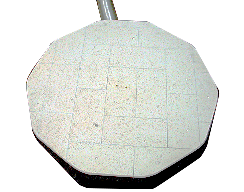
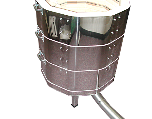
Place the bottom of the kiln on the kiln stand, make sure the holes for the vent, if ordered, line up with the large 3" hole on the kiln stand. Center the bottom brick on the stand. It is not critical how the polygonal corners are oriented to the square stand.
The kiln base positioned on the stand.
- LEVEL THE KILN NOW! Do this before proceeding because at this point it is easy to put a level on the flat bottom. Use metal shims under the legs to accomplish the leveling. We suggest using a carpenter's level for this job. Make sure that the base will not wobble.
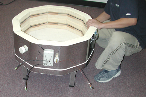
- Place the kiln section with the #5 & #6 on the thermocouple wire on top of the kiln stand (this will not exist for an e23S or e28S so skip to the next step if you have one of those kilns).
Positioning the bottom ring on the base.
- Place the kiln section with the #4 & #3 on the thermocouple lead wire on next.
Positioning the middle ring.
- Place the kiln section with the #1 & #2 on the TC wire on the top ring of the stack.
Positioning the top ring.
- You are now ready to reattach the hinge.
SETTING UP THE HINGE
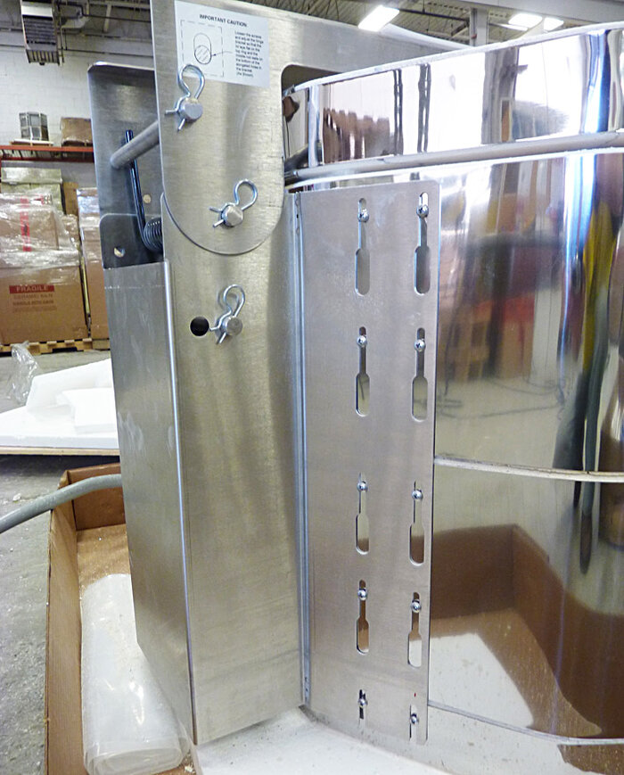
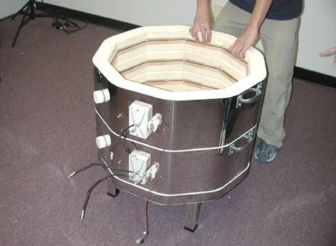
- Notice that on the back of the kiln that the mounting screws for the hinge line up. There should be 20 total, 10 on each side.
The mounting screws lined up.
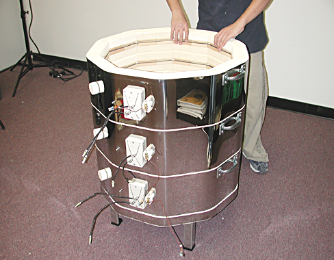
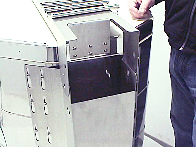
- Reattach the Kiln Bracket to the back of the kiln by dropping it onto the screws on the kiln sections. If the screws on the kiln don't perfectly line up with the holes in the bracket, gently maneuver the bracket until you have all the screw heads into the keyhole slots. Let the bracket drop so that the top of the slots rests against the screws. Do not tighten the screws at this time.
The slots resting on the loose screws.
- Set the Lid onto the top ring of the kiln, making sure the lid flange fits around the outside of the kiln bracket.
The Lid as ready for hinge installation.
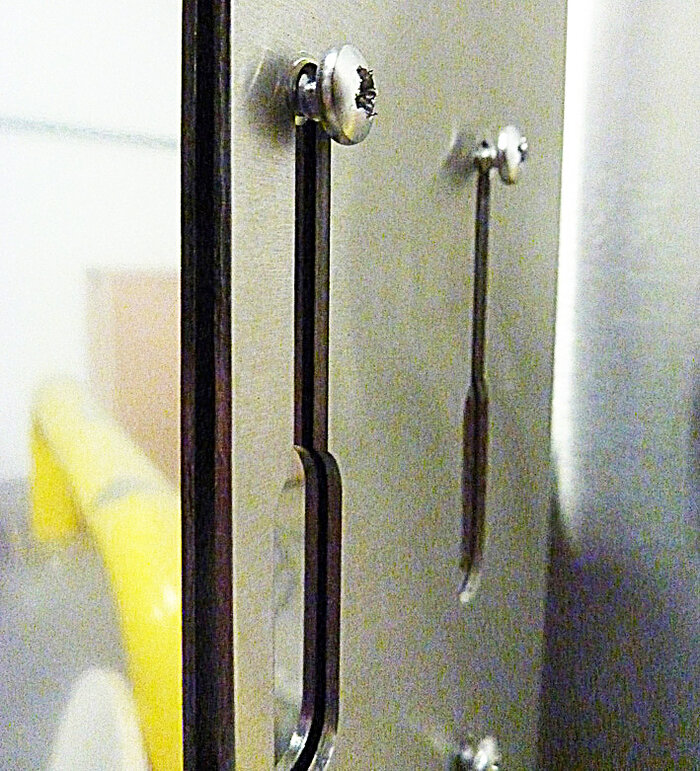
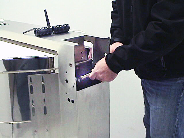
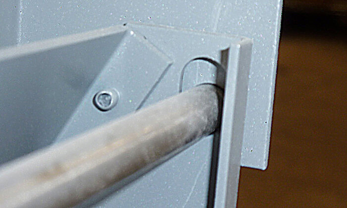
- Slide one of the 3 metal rods through the middle set of holes. You will notice that the holes on the kiln bracket are elongated circles.
Sliding in the middle rod.
- Adjust the height of the bracket by sliding it upwards until the metal rod you inserted in the middle set of holes rests on the bottom ends of the elongated circular holes.
Positioning the hinge bracket.
- Tighten each of the 20 screws to secure the Hinge Bracket in this position.
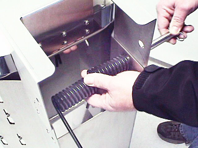
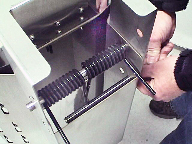
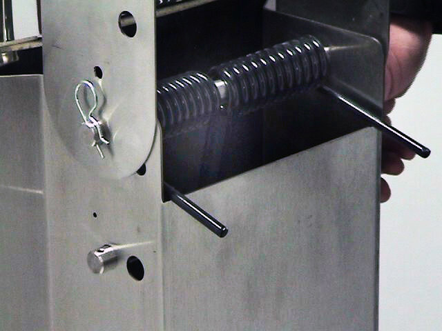
- Remove the middle metal rod. Hold the two hinge springs on the inside of the hinge bracket chamber and slip the rod back through the holes and through the center of the springs. Ensure that the outer spring ends are sitting on either end of the back of the bracket.
Installing the middle rod and springs.

- If you left the bottom metal rod in the kiln bracket ensure that the inner spring ends rest against the inside face of the rod, closest to the kiln body.
- Take the second metal rod and run it through the bottom set of holes on the kiln bracket. Make sure that the inner spring ends stay towards the kiln. This will create tension when the spring is loaded.
Installing the bottom-most rod.
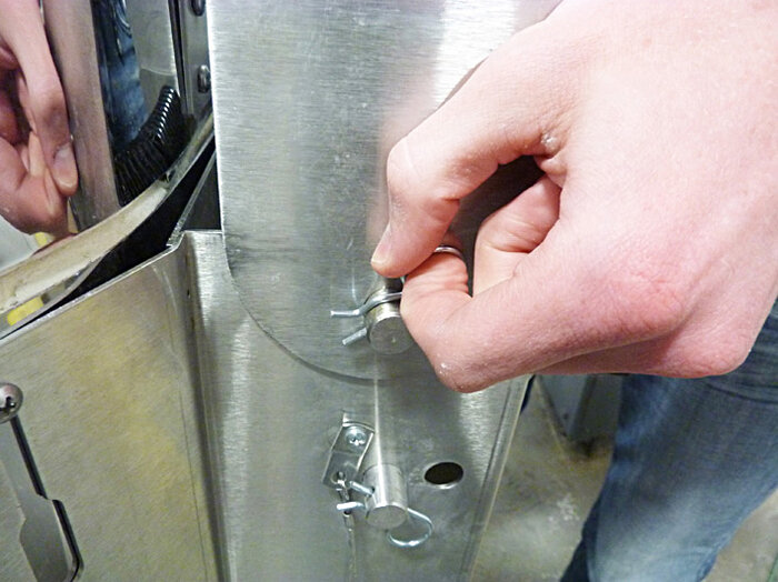
- Once the two metal rods are set in place, set the Cotter Pins in place at each end of the rods.
Setting the cotter pins.
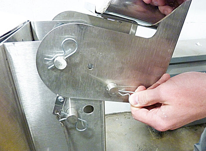
- Carefully raise the lid until the top set of holes passes below the spring ends that are resting on the back of the bracket. Once this occurs, slide the third and final metal rod through the holes on the lid flange.
Installing the top-most rod.
- Once the metal rod is set in place, set the Cotter Pins in place at each end of the rod.
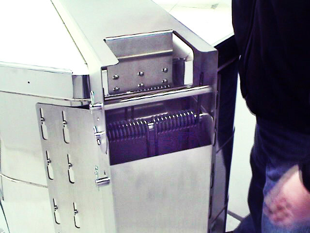
The properly Installed spring hinge open.

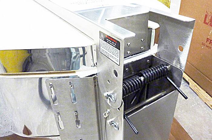
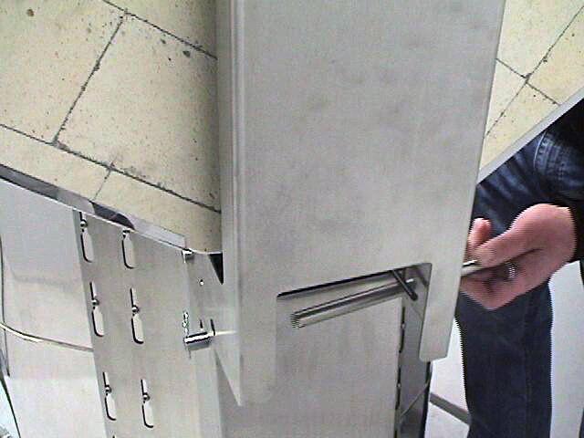
- You will see that when the lid is lowered, this metal rod will catch the spring ends and the weight of the lid will be reduced as the lid is now properly installed.
The properly Installed spring-hinge shown closed.
OPTIONS:
There is another set of holes on the Kiln Bracket if you find that the tension provided from the original configuration is insufficient. Simply try the second set of holes in the same manner as in step 5. You can also use only one spring if you find the spring tension too great.
WARNING: Only use one of the two sets of hole configurations. Never use both.
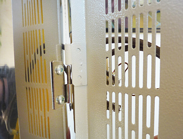
ADJUSTING THE SMALL NON- SPRING HINGE
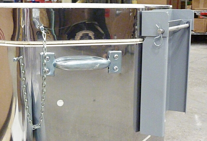
- The non-spring hinge is a very simple system that employs a hinge bar, brackets for the top ring and lid, and support chains between the lid and top ring.
- To take apart the hinge simply pull out one of the cotter pins, remove the hinge bar, and unscrew the screws that hold the support chains in place.
Closed lid with a standard hinge.
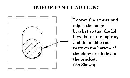
If the brackets are ever adjusted you must ensure that the hinge rod rests on the bottom ends of the elongated circular holes. Move the ring bracket up or down to achieve this result.
Positioning the hinge bracket.
REASSEMBLING THE CONTROL PANEL
- Take the Control Box and Element Cover Box Assembly and position the hinges that are attached to the left of the Element Cover Box above the hinge pieces on the kiln body, to the left of the Element Connection Boards. Lower it into place.
Reattaching the element cover box.
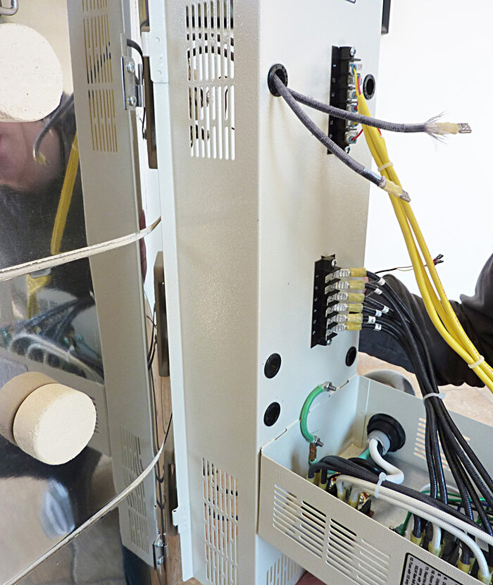
- Leave the assembly swung out away from the kiln body. Push the element and thermocouple wires through their respective holes in the Element Cover Box.
Feeding the wires back through the holes.
- Push the Element Cover Box up against the kiln. Insert and tighten the screws back into the right side of the Cover Box.
Tightening the element cover box screws.
- Attach all the wires to their proper place on the terminal boards. They are numbered for convenience.
Wires properly reinstalled.
- Close the Control box and screw in the two screws that hold it in place at the top of the Element Cover Box.
Tightening the control box screws.
If you removed the panel separate from the element cover box
- Take the Element Cover Box Assembly and position the hinges that are attached to the left of the Element Cover Box above the hinge pieces on the kiln body, to the left of the Element Connection Boards. Lower it into place.
Reattaching the element cover box.
- Leave the assembly swung out away from the kiln body. Push the element and thermocouple wires through their respective holes in the Element Cover Box.
Feeding the wires back through the holes.
- Push the Element Cover Box up against the kiln. Insert and tighten the screws back into the right side of the Cover Box.
Tightening the element cover box screws.
- You are now ready to reattach the hinge portion of the dynatrol panel.
REATTACHING CONTROL BOX
- Place the tabs on the control panel box back in to the appropriate slots on the element cover box.
Reattaching the control panel box.

- Reattach the ground wire to the ground lug from the control box to the element cover box.
Reattaching the ground wire.
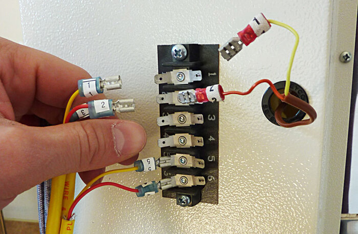
- Reattach all power wires to the appropriate numbered terminals.
Power wires properly reinstalled.
- Reattach the thermocouple wires to the appropriate numbered terminals making sure yellow goes with yellow and red goes to red. Make sure to push the slip-on terminals all the way onto the tabs on the connection terminals.
Thermocouples wires properly reinstalled.
- Raise the panel and replace the two screws at the top and tighten making sure to keep the thermocouple lead wires and the power connect wires from getting pinched in the panel.
Tightening the control box screws.
- Your kiln is now fully assembled and ready to operate.
e14S-3:
- Three 12'' full round shelves
- Four each 1/2'', 1'', 2'', 4'', and 6'' square posts
- A pair of temperature-resistant gloves
e18S-3 or e18M-3:
- One 15'' full round shelves and four 15'' half shelves or six 15" half shelves
- Four each 1/2'', 1'', 2'', 4'', and 6'' square posts
- A pair of temperature-resistant gloves
For an e18T-3:
- Two 15'' full round shelves and four 15'' half shelves or eight 15" half shelves
- Six each 1/2'', 1'', 2'', 4'', 6'' and 8'' square posts
- A pair of temperature-resistant gloves
For an e23S-3 or an e23M-3:
- Six 20'' round half shelves
- Six each 1/2'', 1'', 2'', 4'', 6'' and 8'' square posts
- A pair of temperature-resistant gloves
For an e23T-3, e23M-3, SM23T-3, JD230-3, JD230-JH, or eQ2327-3:
- Eight 20'' round half shelves
- Six each 1/2'', 1'', 2'', 4'', 6'' and 8'' square posts
- A pair of temperature-resistant gloves
For a JD236-3:
- Ten 20'' round half shelves
- Six each 1/2'', 1'', 2'', 4'', 6'' and 8'' square posts
- A pair of temperature-resistant gloves
For a JD245-3:
- Ten 20'' round half shelves
- Six each 1/2'', 1'', 2'', 4'', 6'' and 8'' square posts
- A pair of temperature-resistant gloves
For an e28S-3 or e28M-3:
- Six 25-1/2'' half shelves
- Six each 1/2'', 1'', 2'', 4'', 6'' and 8'' square posts
- A pair of temperature-resistant gloves
For an e28T-3, JD2927-3, JD2927-JH, or eQ2827-3:
- Eight 25-1/2'' half shelves
- Six each 1/2'', 1'', 2'', 4'', 6'' and 8'' square posts
- A pair of temperature-resistant gloves
For an eQ2836-3 or JD2936-3:
- Ten 25-1/2'' half shelves
- Six each 1/2'', 1'', 2'', 4'', 6'' and 8'' square posts
- A pair of temperature-resistant gloves
For a JD2945-3:
- Twelve 25-1/2'' half shelves
- Six each 1/2'', 1'', 2'', 4'', 6'' and 8'' square posts
- A pair of temperature-resistant gloves