
Genesis Operation Manual
Genesis 2.0 & Genesis Mini - Model LT1120
PDF INSTRUCTIONS: See this link for a PDF version. (This online version can also be printed and will print QR codes for the videos.)
INTRODUCTION
This manual covers the operation of the Genesis 2.0 & Genesis Mini LT1120 kiln controllers. The Genesis is a versatile touchscreen controller that regulates the temperature in your kiln so you can fire various products like ceramics, glass, jewelry, and more. The Genesis has preset ceramic programs with cone fire programming, preset glass firing profiles, 30 custom programs, Wi-Fi capabilities for software updating, built-in diagnostics, and maintenance logging, among other new features.
PRECAUTIONS
- The controller is used to control temperature; it is not a safety device.
- Do not operate the controller in temperatures above 160°F.
- Always supervise your kiln during a firing.
- The controller contains electronic components that are sensitive to static electricity. Before handling the controller, dissipate any static charge you may have by touching metal or a screw on the controller panel, the electrical box, the kiln lid, or some other grounded object.
- Always check the position of the thermocouple probe before starting a firing. The current temperature displayed on the controller is measured at the end of the thermocouple, which must protrude about 1” to 1-1/2” into the firing chamber. Seal the opening around the thermocouple with ceramic fiber or similar material if necessary.
- Always review the current program before firing to ensure the correct profile is programmed.
- Ensure the kiln and the areas around the kiln are clear of combustible material. See hotkilns.com/cautions/clearances-flammable-surfaces
VIDEO GUIDES
Supplementing this written manual are numerous video guides and demonstrations. Relevant videos will be inserted throughout this page. For a complete video library, please visit hotkilns.com/support/operation
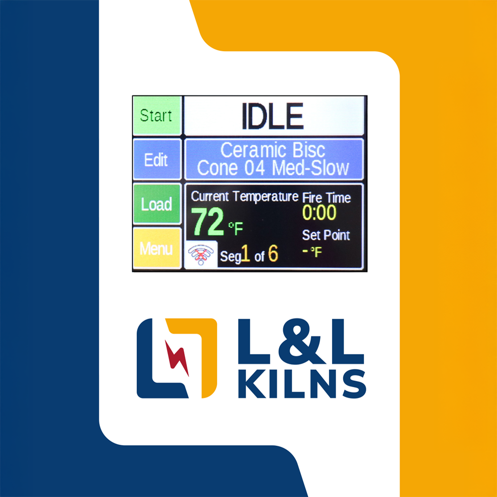
Home Screen Overview

See https://www.youtube.com/video/kRJqg_9_Pb8
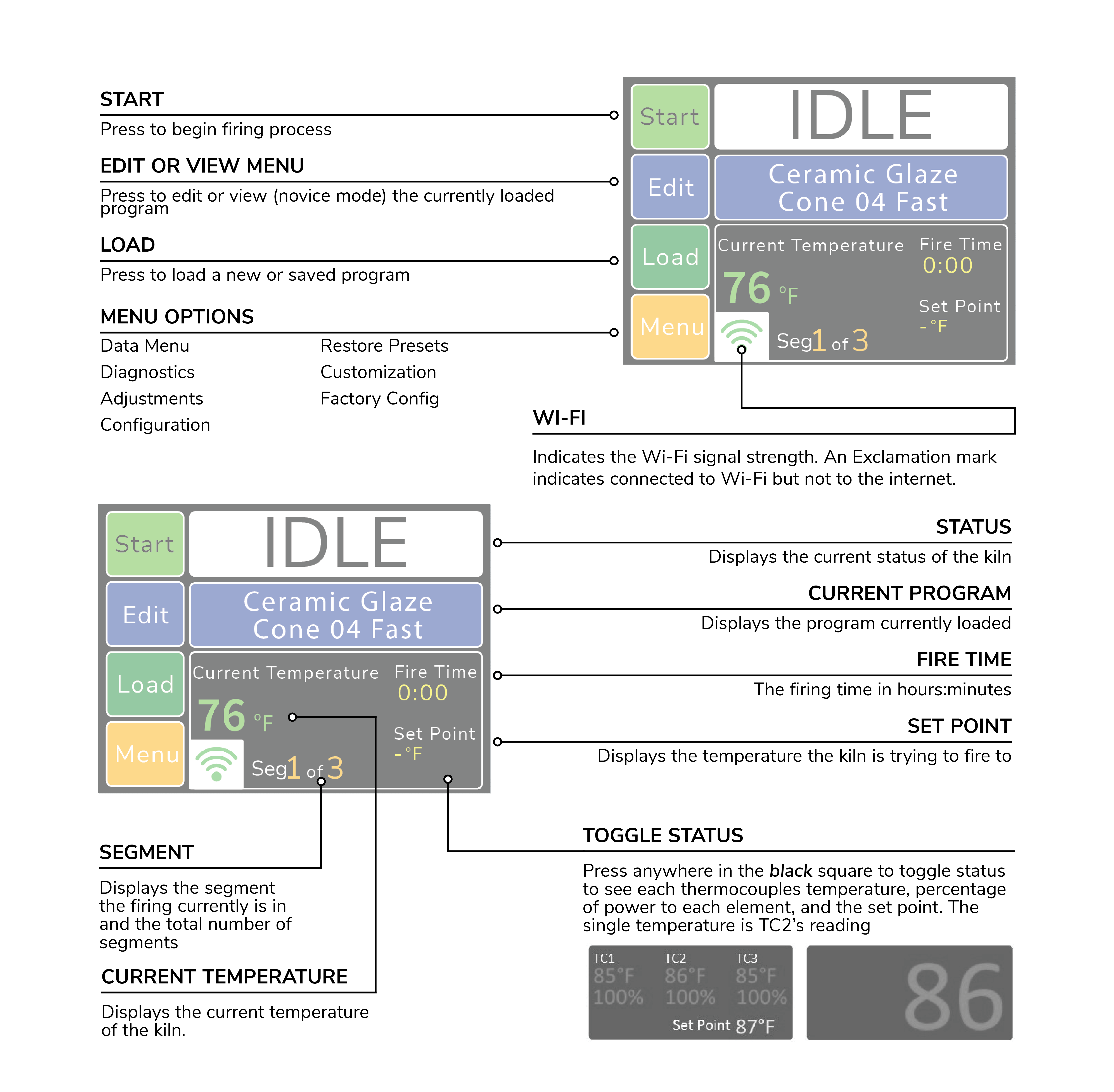
Figure 1: Home Screen Overview
Quick Start
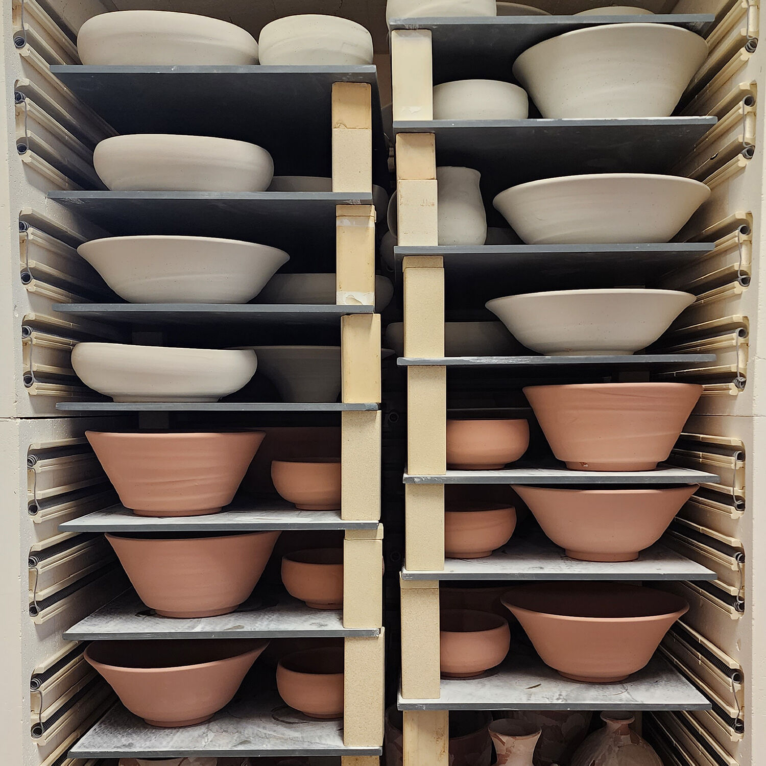
First Firing Of The Kiln

See https://www.youtube.com/video/TMpWNf1tGjY
The purpose of the first firing is to put a protective oxide layer on the elements and thermocouple. The first firing is done without ware in the kiln that might give off fumes that contaminate the elements. This first firing should have shelves and witness cones. The witness cones should be on the middle of the shelf nearest the center of the kiln. If your kiln is supplied with cones, the programmed cone number should match the cones provided, or you may use a cone of your own choice for the first firing. The example below is for a cone 04 firing, but if you use a cone other than 04, substitute that cone number in the programming.
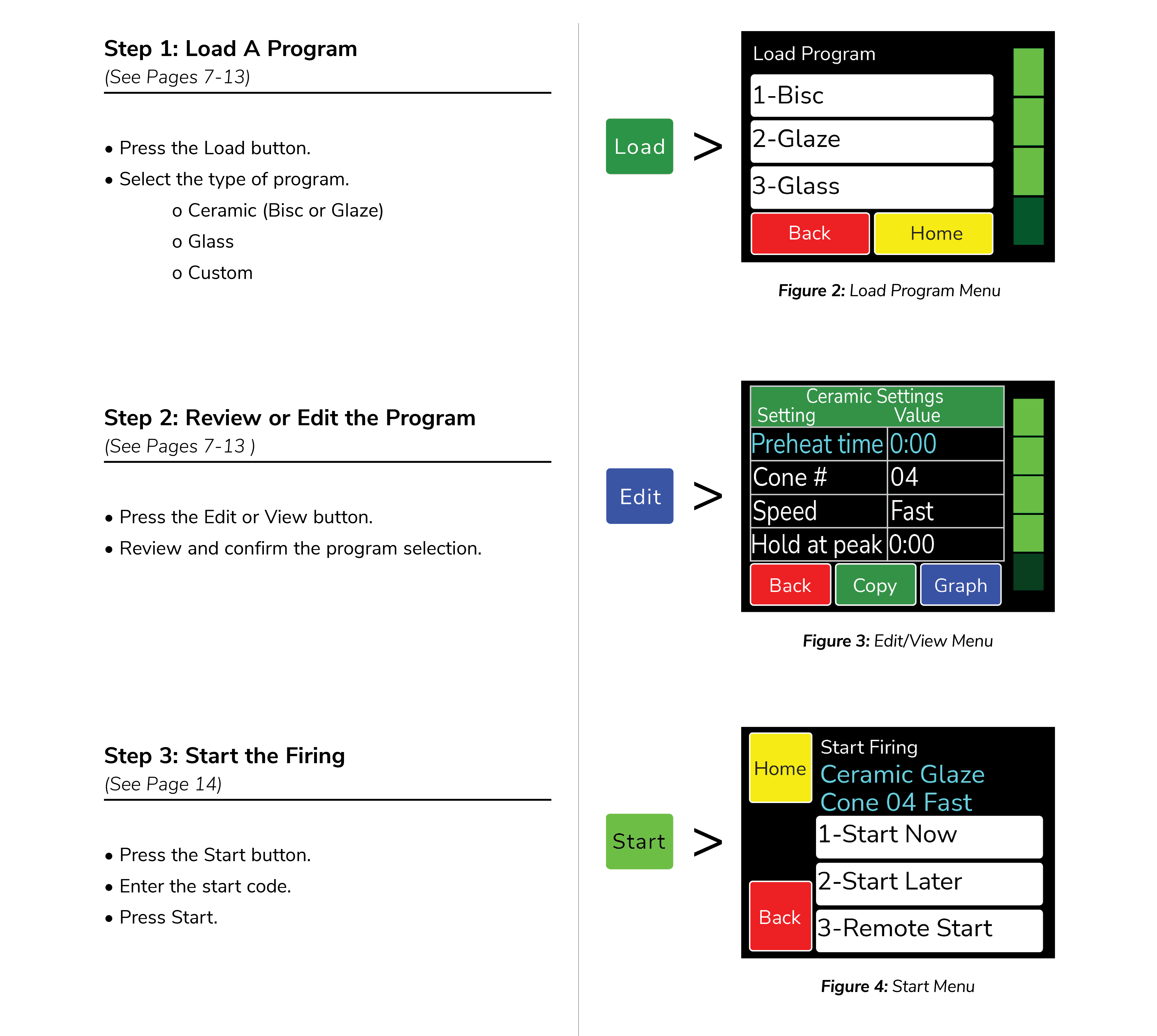
Program the Controller
This example is for a Medium Glaze to cone 04 with no hold time at the end of the firing. The example below is for programming in Novice Mode.
Step: 1
Display: Home Screen
Press: LOAD
Comment: You’re ready to load the Ceramics program into the controller.
Step: 2
Display: What are you firing?
Press: Ceramics
Comment: Choose from Ceramics, Glass, or Other. Choose Ceramics for the first firing of the kiln.
Step: 3
Display: Cone Number 04 / Temperature 1945
Press: NEXT
Comment: Use the scroll bar on the right until Cone 04 is displayed.
Step: 4
Display: What Speed?
Press: Medium - Glaze larger pieces or bisc thin
Comment: The firing time for a medium Glaze firing generally ranges between 7 to 8 hours.
Step: 5
Display: Preheat Time?
Press: None - Thin, bone dry bisc or glaze
Comment: No preheat time is needed.
Step: 6
Display: Program Loaded: CERAMIC GLAZE / CONE 04 FAST
Press: OK
Comment: Returns to Home Screen at IDLE.
Review Program Before the Firing
Press the View key to review the loaded program. Check that the settings are correct. If you’d like to change the alarm, go to Adjustments under Menu. When ready to fire, press BACK to return to the Home Screen.
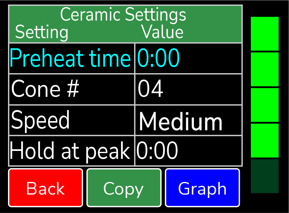
Figure 5: First firing program example. Use the green scroll bar on the right to see more options.
Start The First Test Firing
Step: 1
Display: Home Screen
Press: START
Comment: The kiln is ready to be fired.
Step: 2
Display: Start Firing CERAMIC GLAZE CONE 04 FAST
Press: 1-Start Now
Comment: This kiln is ready to be fired and the start code must be entered.
Step: 3
Display: Enter Start Code
Press: 1
Comment: The controller’s default start code is 1.
Step: 4
Display: Enter Start Code
Press: GO
Comment: Upon pushing GO, the firing will begin. You will hear clicking when the relays cycle power to the elements. This firing will take around 6 to 7 hours.
Step: 5
Display: COMPLETE – CLR returns to idle.
Press: CLR
Comment: The firing has gone to complete. The current temperature, fire time, segment, and set point is displayed.
Step: 6
Display: Home Screen
Press: (none)
Comment: Pressing clear returns the controller to IDLE. You may open the kiln when the temperature has cooled to 150°F.
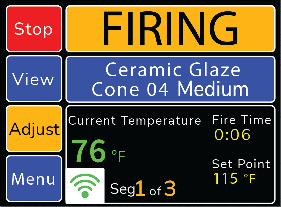
Figure 6: Sample firing screen. For more information about a firing in progress, see Adjustments During A Firing
Review the Results
A properly bent cone indicates that the kiln is functioning properly and accurately. The tip of the cone will be level with the top of the cone’s base when fired properly. The diagram below will give you an idea of a properly fired, under fired, and over fired cone. Some variations from a proper bend is expected and can be compensated for with the cone offset adjustment for each particular cone number based on test firings.

Figure 7: Samples of under fired, properly fired, and over fired cones.
Ceramics Programming (Bisc Or Glaze)
Programming in Novice mode is the easiest method to program the controller to fire ceramics. Programming consists of choosing a cone number, firing speed, and a preheat time. The firing speed is chosen by the type of firing and thickness of the clay used. All 4 speeds below will calculate the firing rate at the end of a firing and adjust the final temperature for correct heat-work.

See https://www.youtube.com/video/ofV-CKI-1Pw
Ceramics Programming – Novice Mode ON:
Step: 1
Display: Home Screen
Press: Load
Comment: You’re ready to load a different program into the controller memory.
Step: 2
Display: What are you firing?
Press: Ceramics
Comment: Choose from Ceramics, Glass, and Other. Choose Ceramics for a bisc or glaze firing.
Step: 3
Display: Cone Number XX Temperature XXXX
Press: Next
Comment: Use the scroll bar to choose the desired cone number. Cone numbers starting with 0 are lower temperature. Don’t mix up cone 6 with cone 06!
Step: 4
Display: What Speed?
Comment: Choose the firing speed (Fast, Medium, MedSlo, or Slow).
Press: Fast
Comment: Fast is the fastest firing speed. Typically 4-5 hours for thin glaze, china paint, or decal firings.
Press: Or Medium
Comment: Medium is for thicker glaze ware or bisque of very thin pieces. Typically 6-8 hours, depending on cone.
Press: Or MedSlo
Comment: MedSlo is for bisque of medium pieces or thinner ware that needs moderate water/carbon burn-out. Typically 9-11 hours.
Press: Or Slow
Comment: Slow is for thicker, hand thrown ware. Extra time for water and carbon burn-out. Typically 13-17 hours. Hand built might need preheat.
Step: 5
Display: Preheat Time?
Comment: Choose a preheat time: None, 4 Hr, 8 Hr, or 12 Hr.
Press: None
Comment: No preheat time for thin, bone-dry bisc or glaze.
Press: Or 4 Hr
Comment: For slightly wet, thicker pieces.
Press: Or 8 Hr
Comment: For thick, wet pieces.
Press: Or 12 Hr
Comment: For hand built, kids pieces, or very wet clay.
Step: 6
Display: Program Loaded:
Press: OK
Comment: Return to Home Screen at IDLE.
Ceramics Programming – Novice Mode OFF:
Step: 1
Display: Home Screen
Press: Load
Comment: You’re ready to load a different program into the controller memory.
Step: 2
Display: Load Program
Comment: Choose between 1-Bisc, 2-Glaze, 3-Glass, or 4-Custom.
Press: 1-Bisc
Comment: The default bisc program will be loaded. Any saved changes overwrite the default program.
Press: Or 2-Glaze
Comment: The default glaze program will be loaded. Any saved changes overwrite the default program.
Step: 3
Display: Program Loaded
Press: OK
Comment: Returns to Home Screen. To make changes to the loaded program, go into the edit menu.
Step: 4
Display: Home Screen
Press: EDIT
Comment: Displays current settings. To change a setting, press that setting, select the new value, then press Save (for example: Preheat Time → type new time → Save).
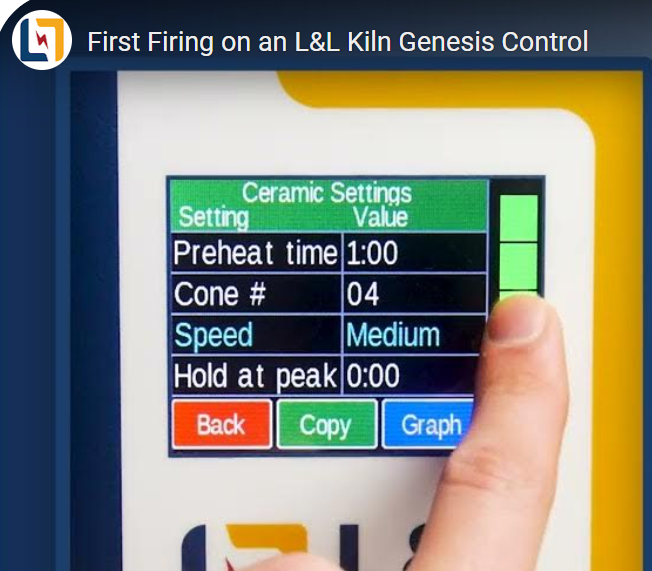
Step: 5
Display: Ceramics Settings
Preheat Time
Cone #
Speed
Hold at Peak Cooling
Press: SAVE or BACK
Comment: Returns to Home Screen at IDLE.
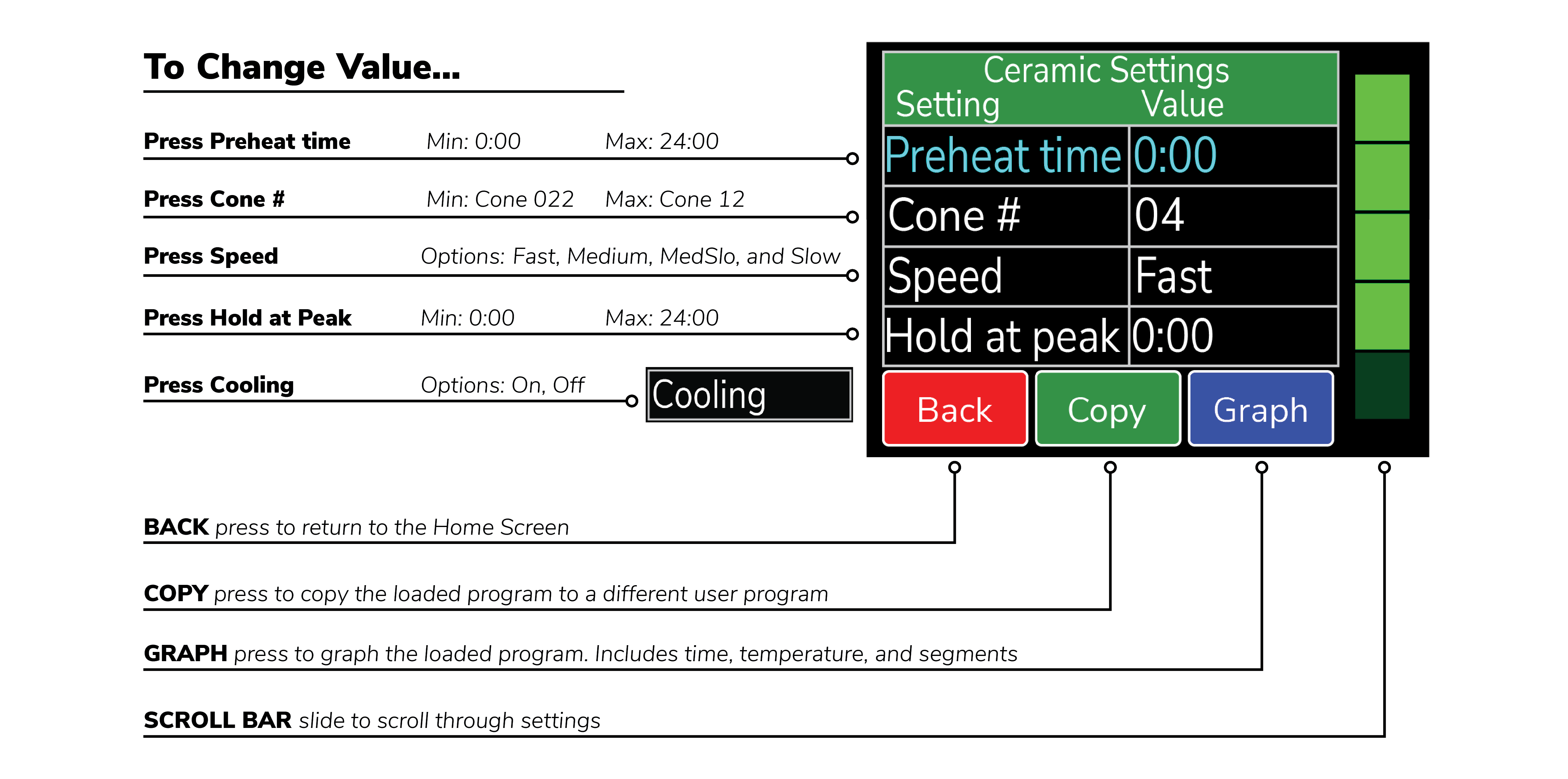
Figure 8: Ceramics programming sample.
Note: When a preheat is selected, the temperature ramps up at 60°F/hour (33°C/hr) to 200°F (93°C) for the amount of time programmed.
Notes for Cooling: Scroll down to select Cooling. Cooling is set to Off unless changed by the user. With cooling turned on, it adds 2 segments on to the end of the firing. The first segment cools the kiln from the top temperature down to 1900°F at a rate of 9999 (As fast as possible). The 2nd and final segment cools the kiln from 1900°F down to 1500°F at a rate of 150°F per hour.
Glass Programming
Programming in Novice mode is the easiest method to program the controller for glass firings. Programming consists of choosing the type of firing, firing speed, and COE (Coefficient of Expansion). The firing speed is chosen by the size of the glass being fired.

See https://www.youtube.com/video/nAYnxop-Vr8
Glass Programming – Novice Mode ON:
Step: 1
Display: Home Screen
Press: Load
Comment: You’re ready to load a different program into the controller memory.
Step: 2
Display: What are you firing?
Press: Glass
Comment: Choose from Ceramics, Glass, and Other. Choose Glass for slumping, fusing, or casting glass.
Step: 3
Display: What type of firing?
Comment: Choose the type of firing, either Slump, Tac Fuse, Full Fuse, or Cast.
Press: Slump
Comment: Slump is used for firing glass pieces that you want to conform to a mold.
Press: Tac Fuse
Comment: Tac Fuse is used for fusing glass that results in softened edges.
Press: Full Fuse
Comment: Full Fuse is used for fusing glass that result in soft, round edges.
Press: Cast
Comment: Cast is used for melting glass pieces together.
Step: 4
Display: What speed?
Comment: Choose the firing speed, either Fast, Medium, MedSlo, or Slow.
Press: Fast
Comment: Fast is the fastest firing speed and is used for glass pieces that are either under 2in. x 2in. or very thin.
Press: Medium
Comment: Medium is used for glass pieces that are under 4in. x 4in. or very thick.
Press: MedSlo
Comment: MedSlo is used for glass pieces that are under 8in. x 8in. or 2 to 3 layers thick.
Press: Slow
Comment: Slow is the slowest firing speed and is used for glass pieces that are over 8in. x 8in. or multiple sheets thick.
Step: 5
Display: Program Loaded:
Press: OK
Comment: Return to Home Screen at IDLE.
Glass Programming – Novice Mode OFF:
Step: 1
Display: Home Screen
Press: Load
Comment: You’re ready to load a different program into the controller memory.
Step: 2
Display: Load Program
Press: 3-Glass
Comment: Choose between 1-Bisc, 2-Glaze, 3-Glass, or 4-Custom
Step: 3
Display: Glass
Comment: Choose the type of glass firing, either Slump, Tac Fuse, Full Fuse, or Cast.
Press: Slump
Comment: Slump is used for firing glass pieces that you want to conform to a mold.
Press: Tac Fuse
Comment: Tac Fuse is used for fusing glass that result in softened edges.
Press: Full Fuse
Comment: Full Fuse is used for fusing glass that result in soft, round edges.
Press: Cast
Comment: Cast is used for melting glass pieces together.
Step: 4
Display: Program Loaded:
Press: OK
Comment: Returns to Home Screen. To make changes to the loaded program, go into the edit menu.
Step: 5
Display: Home Screen
Press: Edit
Comment: Displays the current settings for the firing. To change the settings, press the setting to be changed and select the new setting. For example: To change the speed, press Speed, select the desired speed, and press Save.
Step: 6
Display: Glass Settings Temperature Hold Time Speed Glass COE
Press: Graph
Comment: Press to graph the currently loaded program.
Step: 7
Display: Graph
Press: Table
Comment: Press TABLE to view and edit each individual segment of the firing. Use the scroll bar at the right side of the screen to view each segment in the loaded program. Displays the current settings for each segment of the firing (rate, temperature, and hold time). To change the settings, press the setting to be changed, select the new setting, and press Save. Any saved changes made to the Custom user program will overwrite the default program.
Step: 8
Press: Back
Comment: Returns to Home Screen at IDLE.
Custom Programming
The default custom programs are listed in Appendix C: Custom Firing Default Programs. The Genesis has 30 Custom user programs to store and reuse. User programs 1-12 have 32 segments each, while 13-30 have 8 segments each. Each segment has a firing rate, a temperature, and a hold time. Custom programs can only be edited with Novice Mode set to OFF.

See https://www.youtube.com/video/AQKHkLIpjdY
Custom Programming – Novice Mode ON:
Step: 1
Display: Home Screen
Press: Load
Comment: You’re ready to load a different program into the controller memory.
Step: 2
Display: What are you Firing?
Press: 3-Other
Comment: Choose from Ceramics, Glass, and Other. Choose Other for custom firings.
Step: 3
Display:
Other
User 1
User 2
User 3
Press: UserX-
Comment: Using the scroll bar on the right side of the screen, scroll until the desired program is displayed. For a complete list of the default programs, see Appendix C: Custom Firing Default Programs.
Step: 4
Display: Program Loaded: CUSTOM UserX
Press: OK
Comment: The selected custom program has been loaded.
Step: 5
Display: Home Screen
Press: View
Comment: Use the scroll bar at the right side of the screen to view each segment in the loaded program. There is a specific rate, temperature, and hold time for each segment. You cannot add, delete, or change segments when Novice Mode is activated.
Step: 6
Display: UserX – #, Rate, Temp, Hold, F
Press: Back
Comment: Returns to Home Screen at IDLE.
Custom Programming – Novice Mode OFF:
Step: 1
Display: Home Screen
Press: Load
Comment: You’re ready to load a different program into the controller memory.
Step: 2
Display: Load Program
Press: 4-Custom
Comment: Choose between 1-Bisc, 2-Glaze, 3-Glass, or 4-Custom.
Step: 3
Display: Custom
Press: UserX-
Comment: Using the scroll bar on the right side of the screen, scroll until the desired program is displayed. For a complete list of the default programs, see Appendix C: Custom Firing Default Programs.
Step: 4
Display: Program Loaded: Custom UserX
Press: OK
Comment: The selected custom program has been loaded.
Step: 5
Display: Home Screen
Press: Edit
Comment: To make changes to the loaded program, go into the edit menu. Use the scroll bar at the right side of the screen to view each segment in the loaded program. Displays the current settings for each segment of the firing (rate, temperature, and hold time for each segment). To change a setting, press the setting to be changed and select the new setting. For example: To change the rate for Segment 1, press the temperature listed under Segment 1’s rate, type in the new temperature, and press Save. Any saved changes made to the Custom user program will overwrite the default program.
Step: 6
Display: UserX- #, Rate, Temp, Hold, F
Press: Back
Comment: Returns to Home Screen at IDLE.
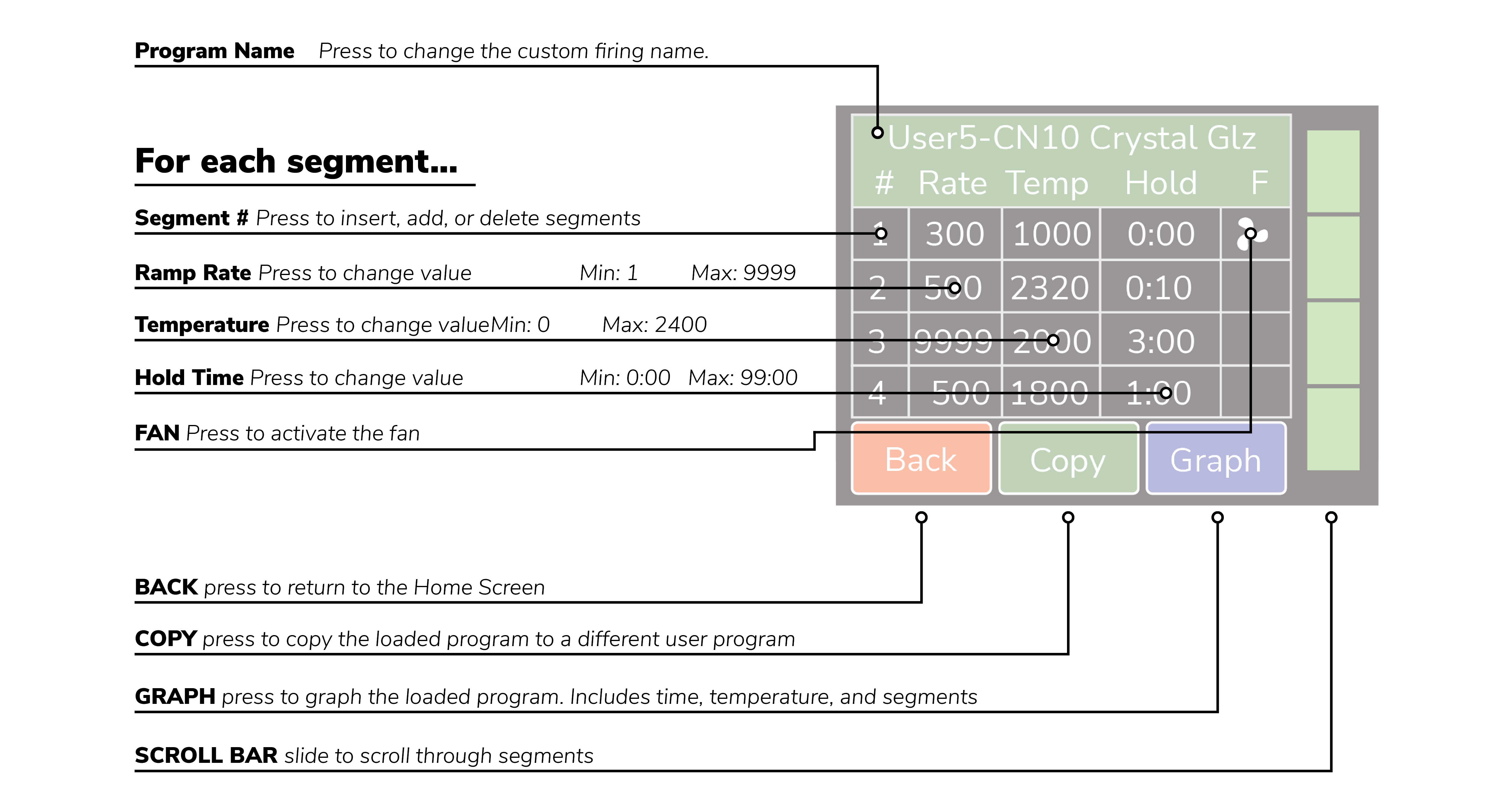
Figure 9: Custom programming sample.
Notes For Custom Programming:
- A firing will start in the earliest segment with a temperature greater than the current kiln temperature. If the current kiln temperature exceeds all segment temperatures, the controller will go directly to complete.
- To ramp up or down at the maximum rate, enter a rate of 9999.
- To program a down ramp, enter the rate/hour then a temperature below the previous segment’s temperature.
- It is best to write out the firing profile that you plan to program before you begin programming. A blank form for writing your firing programs can be found in Appendix D: Blank Firing Program. Photo-copy as needed.
Calculating Ramp Rates for Custom Firing
If you want to go from room temperature to 750°F in 3 hours, use this method to calculate the ramp rate. Take the temperature that you want to go to (750°F) minus the starting temperature (70°F – approximate room temperature) to get the number of degrees you want to increase in 3 hours (750 – 70 = 680). Divide this number by the time you want to get to 750 to give you the ramp rate (680°F ÷ 3 hrs = 227°F/hr). If you want to add another segment to go from 750°F to 1000°F in 4 hours, the same procedure is used. Take the end temperature minus the starting temperature (1000 – 750 = 250) and divide this number by the number of hours to reach 1000°F (250°F ÷ 4 hrs = 63°F/hr).
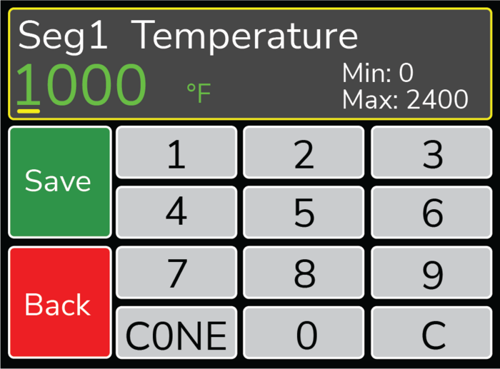
Figure 10: During a Custom Firing, you can enter the desired temperature or press CONE. Choose the desired Cone Number and the controller will enter the corresponding temperature.
Custom Ceramics Program
Writing your own ceramics program combines the versatility of the Custom program and the heat-work calculation of a ceramics firing. It is a great way to get custom heating and cooling rates and still have the controller do the heat-work calculation to get the correct cone bend regardless of firing rate. The steps to write your own cone fire are the same as entering a Custom program except when programming the top temperatures, press the “CONE” button, scroll until the desired cone number is displayed, and press “SAVE”. The selected cone’s top temperature will be displayed under Temp for that segment. The cone temperature can be entered into any segment so you can also have cool down segments in the program. For blank tables to write down your custom programs, see Appendix D.
Start A Firing
Press “Start” to open the Start Firing Screen. There are 3 options as to how you’d like to begin the firing. To start the kiln immediately, press “1-Start Now”, enter the start code (Default = 1), and press “Start”. To program the kiln to start in a set amount of time press “2-Start Later”, enter the start code, press “Start”, enter a delay start time of up to 4 hours, and press “SAVE”. CAUTION: Make sure the kiln area will stay clear and safe throughout the delay time and firing time. To arm the controller for a remote start via the KISS program, press “3-Remote Start”, enter the start code, and press “Start”. The controller will now read “REMOTE” at the top. This means the area around the kiln is clear, it’s loaded, and it can be fired at any time from the KISS program.
Operation of the Controller During A Firing
The Genesis controller eliminates much of the “babysitting” that is required with a manual kiln. To ensure the most consistent results from one firing to the next, you should understand how the controller operates and monitor the firing to ensure proper operation. The following diagram and flow chart show the basic components of a kiln’s control system.
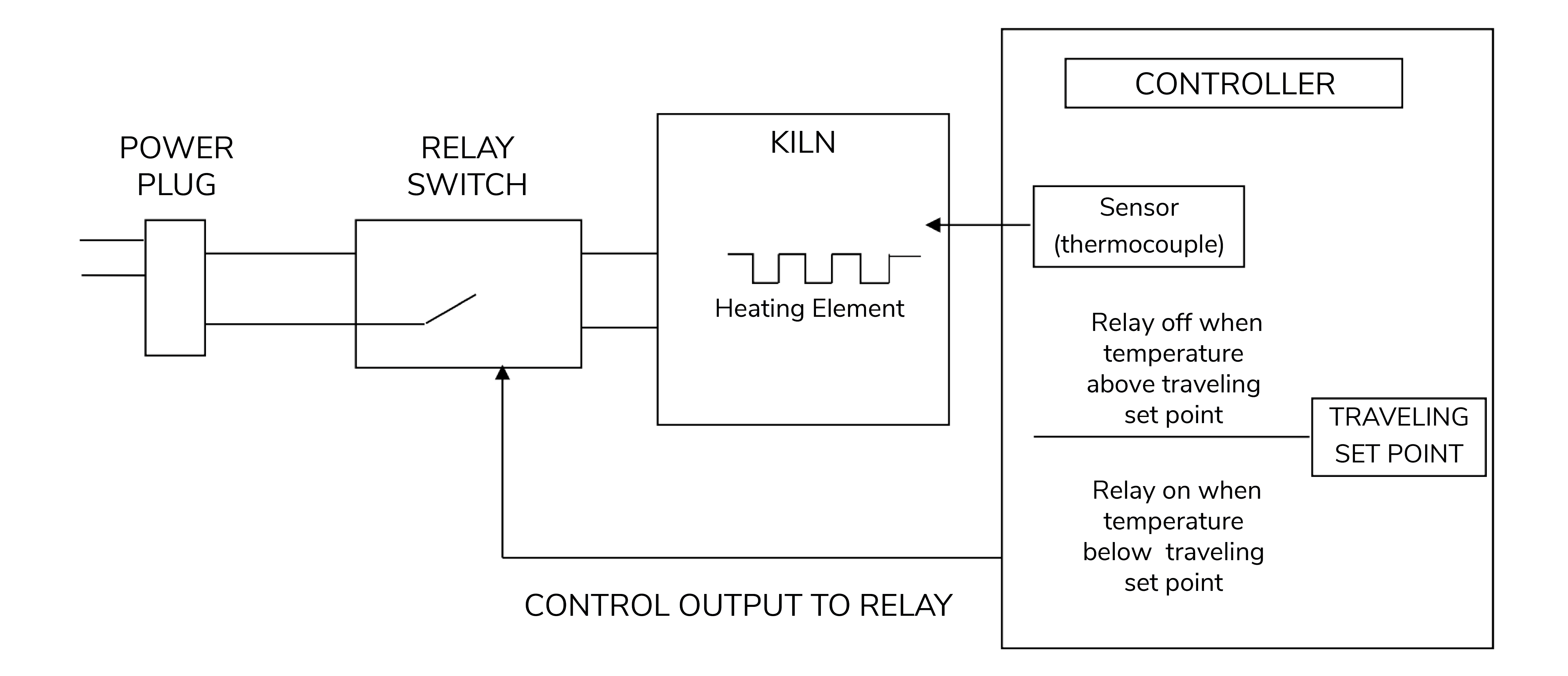
Figure 11: Kiln Operation
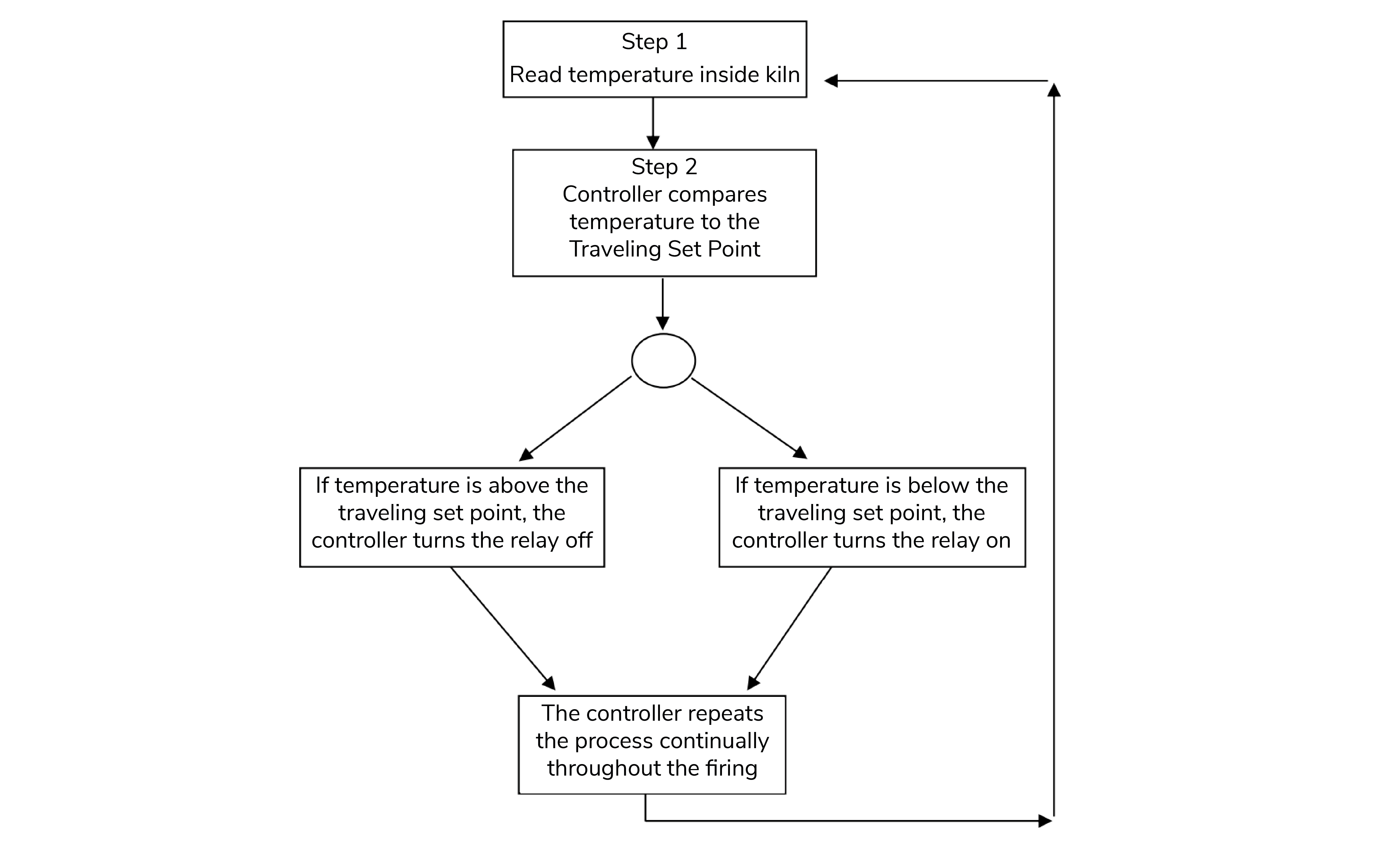
Figure 12: Shows a flow chart of the control algorithm in its simplest form. Like your home thermostat.
The diagram and flow chart show that the kiln control system, in its simplest form, works like your thermostat at home – when the temperature is too cool the heater comes on; when the temperature is too hot the heater turns off. The major components of the control system are the Genesis controller, thermocouple temperature sensor, relay switch, power source, and heating elements. The controller is the brain of the operation; the controller adjusts the traveling set point according to your program, reads the temperature in the kiln, cycles the relay on or off and determines when to end the program.
The thermocouple (T/C) sensor is the first part to inspect when loading the kiln. The tip of the T/C should protrude approximately 1- 1/2” into the firing chamber. Next, “START” is pressed, the controller reads the kiln temperature and uses that temperature as a starting point for a traveling setpoint (also called the local set point). The displayed temperature is the temperature inside the kiln. You should then hear the relay(s) start cycling on and off to keep the temperature near the traveling set point. As the firing progresses the controller moves the traveling set-point according to the programmed firing rate. The displayed temperature should increase with the traveling set-point and the relay will be “on” longer. This sequence continues until the final temperature is reached and the controller turns off the kiln. The display reads “COMPLETE”.
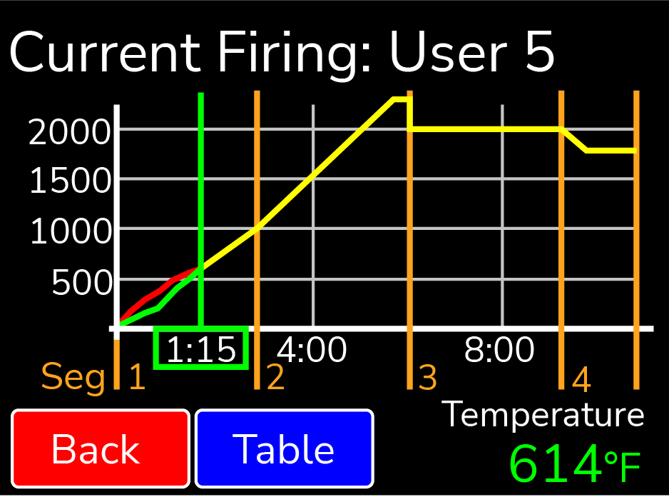
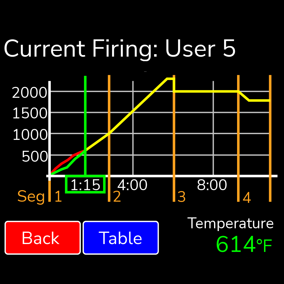
Figure 13: Sample graph of program during a firing
Adjustments During a Firing
Once a firing has been started, the screen will change to the Firing Screen.
You can still view the program and make adjustments to the firing.

See https://www.youtube.com/video/LT6VAD7em_0
Stop
Press STOP at any point in the firing to immediately stop the firing. The controller will return to the Home Screen. To start the program again, simply restart the kiln. The controller will start in the segment with an up-ramp equal to the kilns current temperature. If the kiln does not restart in the segment it was stopped in, press the Adjust button and skip to the desired segment.
View (Applies to Novice Mode)
View the setting for the firing. For a ceramic firing, the preheat time, cone #, speed, and hold time will be displayed. Press the “Graph” button to view the firing as a graph. This includes time, temperature, and segments. To see each individual segment, press the “TABLE” button. Changes or adjustments to the firing can’t be made here once the firing has started. To make adjustments, press the Adjust button.
Graphing Key:
Item on Graph: Orange Vertical Line W/ Number
Meaning: Segment of the firing
Item on Graph: Green Vertical Line W/ Time
Meaning: Current firing time. Represents where the firing is currently, compared to the graph
Item on Graph: Gray Vertical Line W/ Time Below
Meaning: Time at various points throughout the firing
Item on Graph: Yellow Graphing Line
Meaning: Projected path of the firing
Item on Graph: Green Graphing Line
Meaning: Firing’s actual path
Item on Graph: Red Graphing Line
Meaning: Firing’s supposed path (Shown only when actual path and supposed path are not the same)
Item on Graph: Horizontal Gray Line W/ Temperature
Meaning: Kiln Temperature
Edit (Applies to when Novice Mode is Off)
“Edit-on-the-fly”. Pressing the Edit key while firing a custom program will present the table view. Gray segments have already been fired and cannot be changed. All edit features listed on page 12 are available to segments that have not been completed.
Adjust
Press Adjust to make adjustments to the firing while a firing is in progress. Pressing “Add Time” during a hold segment of the firing will add 5 minutes to the hold. It has no effect if the firing is not in a hold when pressed. Pressing “Add Temperature” during a hold segment will increase the hold temperature by 5°F. It has no effect if the firing is not in a hold when pressed. Pressing “Skip Step” will skip the current segment and move to the next in the firing. This feature is used when enough heat work has been done at the current segment and you want to immediately go to the next ramp rate. Pressing “Alarm Temp” allows you to adjust the alarm temperature for the firing. A temperature of 9999 shuts the alarm off.
Menu
The firing menu allows for viewing of statistics and mid-firing diagnostics. By pressing “Diagnostics”, the controller runs a manual diagnostics test during the firing. Pressing “TC Offsets” allows the user to change the temperature offsets for each thermocouple. Minimum: -99°F Maximum: 99°F.
End of Firing – COMPLETE
When the firing is complete, an alarm will sound and the controller will display COMPLETE with the current temperature and firing time. To return to IDLE, press “Clear”. You may open the kiln when the temperature has cooled to 150°F.
Care of Thermocouples
The small metal rods protruding into the firing chamber are the temperature sensors, or thermocouples. Do not let shelves, posts, or ware touch the thermocouples; this could affect the temperature reading. The number of thermocouples will depend on the model of kiln.
The protection tubes covering the thermocouples will help prevent some damage, but make sure to avoid bumping them when loading and unloading as this can still harm the thermocouples or bump them out of the firing chamber.
The thermocouples should protrude into the firing chamber between 1 1/8" - 1 1/2".
Avoid firing clay with high sulfur content. The sulfur erodes the thermocouples making them brittle and easy to break.
Main Menu
By pressing the Menu button on the Home Screen, you’ll be taken to the Menu Screen. The Menu Screen is a list of various options from checking your last firing status, diagnostics, offsets, and controller configuration among other things. To navigate through the Menu options, slide the green scroll bar on the right side of the screen up or down for more options. For more information on each option in the Menu, see the descriptions below:
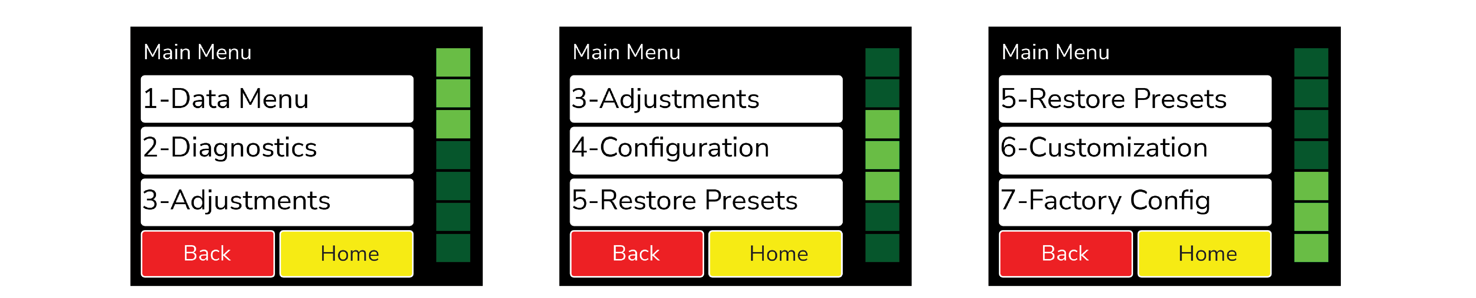
Figure 14: Main Menu
Data Menu
The Data Menu holds 3 types of lists of information: diagnostic information, status information, and kiln information.

See https://www.youtube.com/video/5Z44qX2ZiUw
Last Firing Status
Contains diagnostics information specific to the last firing of the kiln.
Last Error Status
Contains diagnostic information specific to the last error that was encountered by the controller when firing.

See https://www.youtube.com/video/QlKM6Ji0Il0
Factory Diagnostics
Contains diagnostic information from factory. This includes amperage readings for each section, line voltage readings, and board output. This information can be used for comparison when a manual diagnostic test is run.
(Disclaimer: This option is not recommended for L&L kilns due to Zone Control’s effect on amperage readings.)
Last Element Change
Contains diagnostic information from the last new elements diagnostics. This includes amperage readings for each section, line voltage readings, and board output.
(Disclaimer: This option is not recommended for L&L kilns due to Zone Control’s effect on amperage readings.)
Last Manual Diagnostics
Contains diagnostic information from the last manual diagnostics test. This includes amperage readings for each section, line voltage readings, and board output.
(Disclaimer: This option is not recommended for L&L kilns due to Zone Control’s effect on amperage readings.)
Graph Past Firing
Contains the graphs from the last 10 firings. Use the scroll bar to find the desired firing to graph and select it. If Wi-Fi is connected during the firing, the month and day will be displayed next to the firing. If Wi-Fi is not connected, it will read 0/0 after the name of the firing.

See https://www.youtube.com/video/_LSSLDlrW9w
Kiln Info
Contains the firmware version plus the serial number and mac address for registering and viewing your kiln at www.bartinst.com and using the Bartlett KilnAid app.

See https://www.youtube.com/video/91BnfralR7U
Diagnostics
Board Temperature
Displays the current board temperature. Displaying the board temperature is a diagnostics function to check the operation of the board. The safe range for board temperature is between 0°F - 160°F. Any temperatures below or above that range may cause damage to the controller.
Run Manual Diagnostics
This is used to manually begin a diagnostics test. It turns on each section of elements to read amperages and voltage. The results are stored under Data Menu – Last Manual Diagnostics.
New Element Diagnostics
Run New Element Diagnostics when the elements have been changed to record amperages and voltages for the new element. The results are stored under Data Menu – Last Element Change.
Relay Health
Keep track of the number of on/off cycles of the relays on your kiln. An on/off cycle will be counted as one. When a relay is replaced, press the corresponding zone and press the RESET button to set the number of cycles back to 0.

See https://www.youtube.com/video/ZTXx2BkD-ak
Adjustments
Adjustments allows you to change the Cone and Thermocouple offsets as well as the Alarm temperature and Output 4 Percentage On for the controller.
Cone Offset
Cone offset is used to raise or lower the final cone temperature. The final cone temperature can be raised or lowered a maximum of 99°F (37°C). To correct an under-firing set a positive cone offset. To correct an over-firing, set a negative (-) cone offset. To change the Cone Offset, press “Cone Offset”, and use the scroll bar to select the cone offset. When the correct cone is displayed, press “Edit”, enter the desired offset and press “Save”.

See https://www.youtube.com/video/Nu9b_4SVcQM
Cone Offset Example
Degrees: 20°
Meaning: Raise the final cone temperature by 20°F
Effect: Increases heat work
Degrees: 45°
Meaning: Raise the final cone temperature by 45°F
Effect: Increases heat work
Degrees: -15°
Meaning: Lower the final cone temperature by -15°F
Effect: Decreases heat work
Degrees: -35°
Meaning: Lower the final cone temperature by -35°F
Effect: Decreases heat work
Thermocouple Offset
Thermocouple offset is used to raise or lower the temperature indicated by the thermocouples. This is generally used to balance the heat-work in a zone controller kiln The maximum TC Offset is 99°F (37°C). To correct an under-firing set a negative TC Offset. To correct an over-firing, set a positive TC Offset. To change the TC Offset for thermocouple 1, press “TC Offsets”, press “TC1 Offset”, enter the desired number and press “Save”. Repeat for TC2 Offset and TC3 Offset if needed.

See https://www.youtube.com/video/2saVmMuZmfM
Alarm Temperature
Set the alarm temperature for the kiln. To set the alarm before the firing, press “Set Alarm”, type the desired alarm temperature, and press “SAVE”. The default alarm temperature is 9999°F (Off). The alarm setting will change as you change the loaded program. For example, the USER1 program is loaded and the user sets the alarm to 2400°F. The user then loads the USER2 program and sets the alarm to 1700°F. If the user loads USER1 again, the alarm temperature will change back to 2400°F automatically.

See https://www.youtube.com/video/eFXekMFdd6I
Out 4 Percent On
Sets the “on time” Output 4 as a percent of output three’s “on time”. Only used when enabled by L&L Kilns.
End of Hold Alarm
When enabled, the alarm will sound when a hold has come to an end. To stop the alarm, simply tap anywhere on the screen. To enable the End of Hold Alarm, press “Enable” and press “SAVE”.
Start of Hold Alarm
When enabled, the alarm will sound when a hold has started. To stop the alarm, simply tap anywhere on the screen. To enable the End of Hold Alarm, press “Enable” and press “SAVE”.

See https://www.youtube.com/video/Af-P4RU07dw
PID Gain
Leave this setting alone unless instructed by L&L or Bartlett.
Dampening Factor
Leave this setting alone unless instructed by L&L or Bartlett.
Configuration
Novice Mode
The Genesis may come set in Novice Mode depending on model of kiln. Novice Mode is meant for beginner users to make programming easier. For more advanced programming, Novice Mode can be turned off. To turn Novice Mode off, select “Off” and press “Save”.

See https://www.youtube.com/video/K7WPwfBYzFM

See https://www.youtube.com/video/kk5IHSuj7oc
Communications
Set up Wi-Fi for Firmware download and KISS ID for monitoring firings fro your PC. (Additional computer software required for PC monitoring)
- Kiss ID
Each controller to be monitored must have a unique KISS ID number ranging from 1 to 50. See KISS manual for details.
- Enable Wi-Fi
Enable or disable the Wi-Fi feature. Off turns Wi-Fi capabilities off at all times. On When Firing enables Wi-Fi only when a firing is in progress. Always On turns the Wi-Fi on anytime it is within range of a setup Wi-Fi connection.
- Wi-Fi Setup
To set up Wi-Fi for the Genesis, press “Wi-Fi Setup” and the controller will scan for nearby networks. Select your desired network and enter the password (if required) and press “Save”.
***For security reasons, we highly recommend that the user place all controllers into a separate logical network or VLAN, separate from other networks, routers, and hardware.

See https://www.youtube.com/video/Kkz-n3McjC0
- Download Firmware
If your controller is connected to the internet through the Wi-Fi module, by pressing Download Firmware, you will connect to www.bartinst.com to see if any updates are available. Once it has found the firmware, you have the option to update your controller Updating firmware will NOT affect the firing programs.

See https://www.youtube.com/video/cP2rFlLUyUs
- Reset Wi-Fi
Press Reset Wi-Fi when having trouble with the Wi-Fi connection. The controller will reset the Wi-Fi connection and attempt to reconnect to your currently saved connection.
- Export Log File
Used to activate Server Mode. This allows the controller to “serve” a file to a computer or phone that is on the same access point as the controller. When “Export Log File” is pressed, the controller will list an IP address and a code. Type the address listed on the controller into your internet browser and then enter the code when prompted.
The last 10 firings will be listed and each firing has 2 files – the temperature data and the event file. The temperature file collects data every 30 seconds. The event file collects data any time an “event” occurs such as a hold or an error occurs. Click on the file to be observed to download it.

See https://www.youtube.com/video/oS5r78BhFXI
- Manual Wi-Fi Setup
Used to manually set up a Wi-Fi network that is hidden or otherwise not found when running Wi-Fi Setup. Enter the network name under SSID and press “Save”. Under password, enter the network password and press “Save”.
- Advanced Wi-Fi
Used to adjust DNS settings
- Wi-Fi Diagnostics
Provides information on the Wi-Fi status to aid in troubleshooting connection issies.
Temperature F/C
Choose which temperature scale to use with your kiln, Fahrenheit or Celsius. To change the temperature scale, press “Temperature F/C”, press the desired temperature scale, either “Fahrenheit” or “Celsius”, and press “Save”.

See https://www.youtube.com/video/SvSzRpFlgJY
Error Codes
Turn the error codes on or off for the kiln. The default setting for the controller is On. We recommend you keep the error codes on to protect your firings. They can be turned Off, in special cases, such as jewelry or glass firings where the kiln is left open. They may also be turned off when troubleshooting kiln problems.

See https://www.youtube.com/video/qW07Fd3e2Yo
Number of Zones
Change the number of zones (Thermocouples) the Genesis will control. For the Genesis 2.0 choose: 1, 2, or 3. The Genesis Mini can only be set for 1 zone.

See https://www.youtube.com/video/dW2EFIEQTyg
Output 4 Options – (Usually set as a factory option)
Output 4 has 3 modes for running vent fans (Options A, B, & C), one mode that uses Output 4 to indicate the alarm has triggered (Alarm), and one mode for running elements in the lid or floor of the kiln (Percent).

See https://www.youtube.com/video/nfyz8djCn74
- Option A
Used to control a vent. Output 4 can be programmed to be on or off during each segment of a Custom program.During a Ceramic or Glass program, output 4 come on at the beginning of the firing and turns off after the kiln has cooled to 150°F.
- Option B
Used to control a vent. Output 4 can be programmed to be on or off during each segment of a Custom program. Output 4 comes on at the beginning of a Ceramic or Glass program, off at 1450°F, back on after the firing is complete and the kiln has cooled to 1000°F and finally off again when the temperature is below 150°F.
- Option C
Used to control a vent, an alarm, or other atmospheric control. Output 4 can be programmed to be on or off during each segment of a Custom program. Output 4 is off during Ceramic and Glass programs.
- Alarm
When this option is selected, Output 4 comes on when the alarm is triggered or an error code is encountered.
- Percent
Output 4 can be programmed to be on for a percent of the time Output 3 is on. This option is used when Output 4 controls floor or lid elements. To ensure Output 4 stays off at all times, use this option and set the percentage to zero.
Start Code
The Start Code is entered to start a firing. Enter any 4 number combination and press “Save”. Default = 1. This will be entered anytime the kiln is fired.

See https://www.youtube.com/video/cJjE4Rmd38w
Calibrate Touch
Used to re-calibrate the touch screen if buttons aren’t working properly. Press the “Calibrate Touch” button and follow the onscreen instruction to re-calibrate.

See https://www.youtube.com/video/OB3XuquOtA8
Cost Setup
Enter the cost per kilowatt hour and the wattage for each zone in the kiln. The cost per kilowatt hour has a minimum of $0.001 (1/10th of a penny) and a maximum of $9.999. This information can be acquired from your electric company. The zone wattage has a minimum of 0 and a maximum of 50,000 Watts. This information can be acquired from the nameplate on your kiln. If it a multi-zone kiln, you can enter the kiln’s wattage in Zone 2, or divide the kiln’s wattage and split evenly between the 3 zones.
Example: The cost per kilowatt hour is 16 cents and the kiln is a single zone with a wattage of 16,000. Press Cost/KWH, type in 0.16 and press SAVE. Press Zone1 Watts, type in 0, and press SAVE. Press Zone2 Watts, type in 16,000, and press SAVE. Press Zone 3 Watts, type in 0, and press SAVE.

See https://www.youtube.com/video/NKHbQQUBZdw
Hold Transition
Used to determine the point at which a segment transitions into the next in multi-zone kilns.
- First Zone
When this option is selected, the controller will transition to the next segment when one zone reaches the set point temperature.
- Average of All
When this option is selected, the controller will transition to the next segment when all zone temperatures average out to be the set point temperature.
Indefinite Hold
Turn to ON to activate the Indefinite Hold feature. Once turned on, a user can program an indefinite hold by entering 9999 into a hold time of a segment of a user program. Once set, the controller will hold at that temperature indefinitely until the user stops the program.
Restore Presets
Restore all preset programs and offsets to factory settings.

See https://www.youtube.com/video/pILfUMaeKvw
Restore User Programs
Restore individual User Programs 1-12 back to factory setting. Select the User Program to be restored and press “RESTORE”. This will clear any changes made to that user program from factory settings. Once you press “RESTORE” this cannot be undone. The restored default program will be loaded into the controller upon pressing “RESTORE”.
Reset TC Offsets
Reset thermocouple offsets to factory settings. Default TC Offset = 0 for all thermocouples. To reset: Press “2-Reset TC Offsets” and press “RESTORE”.
Restore Cone Offsets
Reset cone offsets to factory settings. Default Cone Offset = 0 for all cones. To reset: Press “3-Reset one Offs” and press “RESTORE”.
Restore Glass
Restore the Glass firing setting back to factory. Once “RESTORE” is pressed, any changes made to the Glass profiles will be restored back to factory and cannot be undone.
Customization
Customization allows you to change what program menus are available and which set of custom
User profiles to be loaded into the controller either a Mix, Heat Treat, or PMC.

See https://www.youtube.com/video/ANfW2W6nnxM
Ceramic Menus
Allows the user to enable or disable the ceramic programming menus. When disabled, the Bisc and Glaze programs will be removed under “Load Program”.
Glass Menus
Allows the user to enable or disable the glass programming menus. When disabled, the glass programs will be removed under “Load Program”.
User Library
Allows the user to change which customizable user programs are to be loaded into the controller. Options for programs include “Mix”, “Heat Treat”, and “PMC”. For a list of the User Libraries, see Appendix C.
Factory Configuration - "Hidden Menu"
Factory Configuration, or the "Hidden Menu", is used by L&L Kilns to set kiln specific parameters for the controller such as thermocouple type, top temperature, and board temperature.
Contact service@hotkilns.com before making any changes that might damage the kiln.
To access the Hidden Menu, select "Factory Config", enter the code number 443 and press "Save".
TC Type
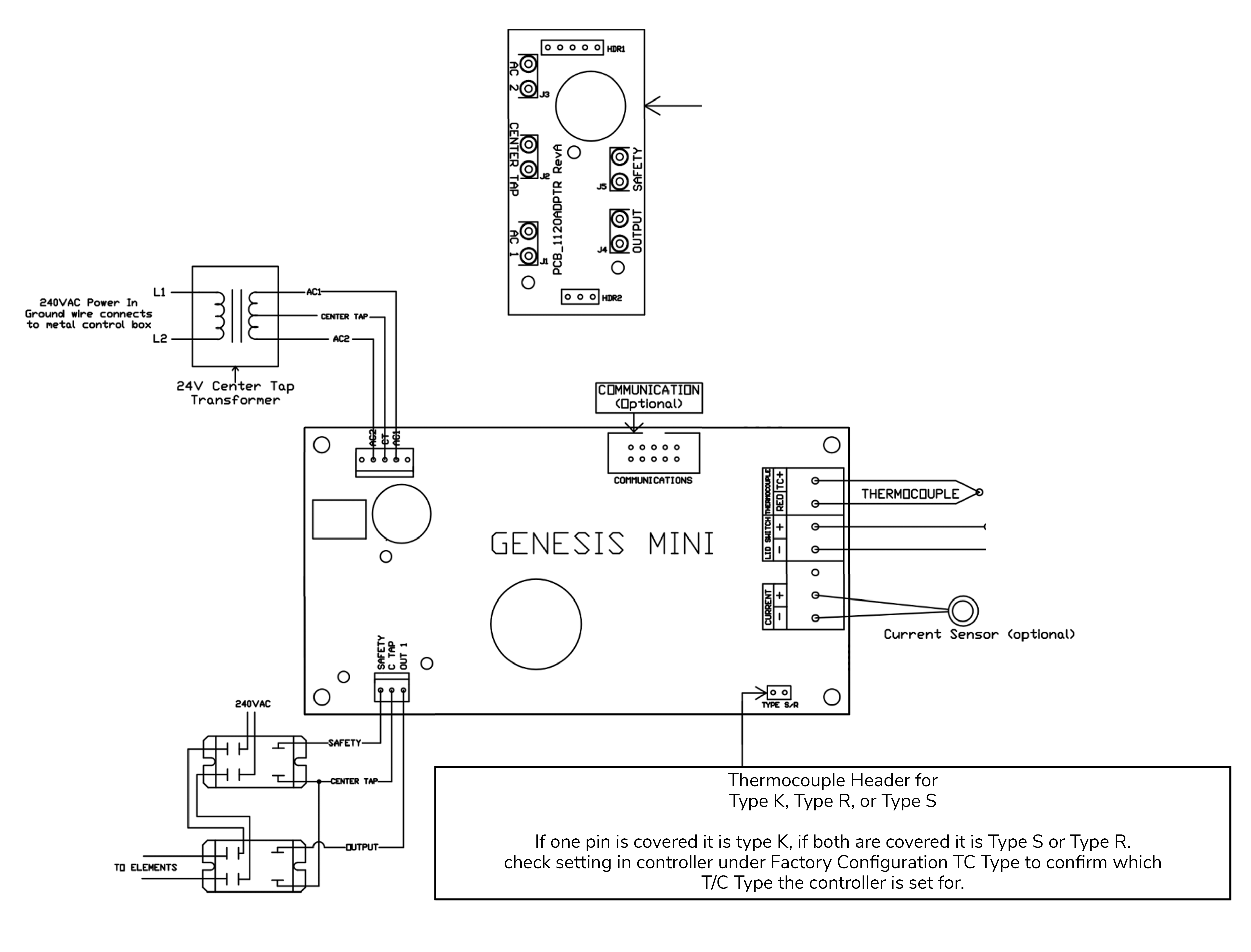
Change the thermocouple type used with the controller from Type K, Type S, or Type R. To change thermocouple type in Factory Configuration, select the thermocouple type being used with the controller and press “Save”. When changing from a Type K to a Type S or Type R, you must change the software setting as well as placing a jumper on the circuit board. To change from a Type S or Type R to a Type K requires changing the software setting and removing a jumper from the circuit board.
WARNING: Using a Type S thermocouple and a controller set for Type K will cause serious over-fire. Using a Type K thermocouple and a controller set for Type S will cause an under-fire. Type S thermocouples must use Type S extension wire. Type K thermocouples must use Type K extension wire. If changing thermocouple type be sure to change the extension wire. Make sure the software and jumper settings match the type of thermocouple and extension wire you are using.

See https://www.youtube.com/video/uU4QlWWve2k
Max Program Temperature
Enter the top temperature the kiln is rated for. Set the Max Program Temperature to the maximum temperature rating for the kiln. Check the side of the kiln or the kiln’s manual for its temperature rating. The max setting is 2400°F (1316°C).
Max Board Temperature
Set the maximum temperature the circuit board can reach. Valid temperature are 0 - 250°F. If the board reached a temperature higher than 250°F, it can cause serious damage to the circuit board
SSR Mode
SSR Mode can be turned on when solid state relays are being used on the kiln. When SSR mode is turned on, it cycles the relays at 500 millisecond intervals. This works the same with either 60hz or 50hz systems.
Cycle Time
Sets the output cycle time. The cycle time is the length of time between an output coming on two consecutive times. If the cycle time is set for 14 seconds the output will come on every 14 seconds as needed. Cycle time can be set from 10 seconds to 60 seconds. To change the cycle time in the Factory Configuration Menu, press “5-Cycle Time”, type in the new time, and press “SAVE”.
Current Sensor Rating
The Current Sensor Rating is used to set the number of Amps that will generate a 5V output from a current sensor. Factory default is 50 Amps.
Run Factory Diag.
This is used by L&L Kilns when manufacturing. The factory diagnostics can be used for comparison when future diagnostics tests are ran. To view the amperages and voltages from the Factory Diagnostics test, press the “MENU” button, “1-Data Menu”, then “3-Factory Diagnostic” to view the results.
Rotate Display
When set to on, the display will rotate 180 degrees. To rotate the screen, press “On” and then press “Save”.
Output Config.
This setting should always be set on Standard, unless prior approval from L&L Kilns.
Mini Version
Use to switch screen formatting from larger Genesis screen to the smaller Genesis Mini screen. This setting should remain set to off for the 2.0 version.
Lid Switch
The Genesis 2.0 has connections for a lid switch. When a lid is connected and the lid switch setting is set to on, the controller will shut power off to the elements, sound an alarm, and give a LID OPEN message when the lid is opened during a firing. When a lid is connected and this is set to off, the controller will continue to fire as scheduled, even when the lid is opened.
Output 3 Alarm
The Genesis 2.0, when in single zone mode and Output 3 Alarm is enabled, output 3 will turn on and off with the alarm. It is used by some to run a louder alarm.
Appendix A: Error Codes
If you get an error code, it is important to note the error letter or number. It will help you in diagnosing any problem with the kiln. When an error code is displayed, it will give a short description of the error. Press “Clear” to clear an error code.
List of error codes:
NOTE: THESE ERRORS WILL ONLY BE DETECTED IF THE ERROR CODES ARE TURNED ON:
Error Code: ERROR 1
Description: Kiln temperature increasing slower than 12° F per hour when ramping up
Possible Causes: This is a kiln heating problem, not a controller problem. Do the Full Power Test to check elements and relays. Low or dropping voltage to the kiln could also be the cause. A thermocouple reading incorrectly or improperly placed may also be the cause.
Error Code: ERROR 2
Description: Kiln temperature 50° F above hold temperature
Possible Causes: A relay latched in the “on” position may cause this error. Another possible cause is if the kiln lid is opened for rapid cooling, then closed, such as for glass firings.
Error Code: ERROR 3
Description: Kiln temperature 50° F below hold temperature
Possible Causes: Relay failure.
Error Code: ERROR 4
Description: Kiln temperature 50° F above previous hold when ramping down
Possible Causes: Same causes as for E-2.
Error Code: ERROR 5
Description: Kiln temperature 50° F below traveling set point when ramping down
Possible Causes: Relay failure.
Error Code: ERROR D
Description: Kiln temperature 50° F above traveling set point
Possible Causes: Stuck relay or stuck output. If using zone control, then the outputs or t/c’s may be in the wrong zones.
NOTE: THE ERROR CODE SETTING DOES NOT AFFECT THESE ERRORS:
Error Code: ERROR 0
Description: Kiln temperature increasing slower than 12° F per hour when ramping up
Possible Causes: This is a kiln heating problem, not a controller problem. Do the Full Power Test to check elements and relays. Low or dropping voltage to the kiln could also be the cause. A thermocouple reading incorrectly or improperly placed may also be the cause.
Error Code: ERROR 6
Description: Kiln temperature 50° F above hold temperature
Possible Causes: A relay latched in the “on” position may cause this error. Another possible cause is if the kiln lid is opened for rapid cooling, then closed, such as for glass firings.
Error Code: ERROR 8
Description: Kiln temperature 50° F below hold temperature
Possible Causes: Relay failure.
Error Code: ERROR 9
Description: Kiln temperature 50° F above previous hold when ramping down
Possible Causes: Same causes as for E-2.
Error Code: E--
Description: Kiln temperature 50° F below traveling set point when ramping down
Possible Causes: Relay failure.
Error Code: ERROR A
Description: Kiln temperature 50° F above traveling set point
Possible Causes: Stuck relay or stuck output. If using zone control, then the outputs or t/c’s may be in the wrong zones.
Error Code: ERROR bd
Description: Board temperature too high
Possible Causes: The control box temperature may be too hot or the limit temperature may need to be reset. If the room temperature is very hot, aiming a fan at the control box may decrease the temperature.
Error Code: ERROR E
Description: Hardware error
Possible Causes: Controller will need to be returned to the factory for service.
Error Code: ERROR R
Description: Microprocessor memory does not match program storage memory (EEprom)
Possible Causes: Reprogram and try to fire again. If error persists, controller may need to be returned to factory for service.
Error Code: ERRP
Description: ERRP will display. To clear the display, press “Clear”. The firing in progress will continue.
Possible Causes: Power outage; kiln is still firing.
Error Code: TC FAIL
Description: Thermocouple FAIL indicates one or more t/c’s have failed. If more than one thermocouple is connected, the controller will indicate which thermocouple has failed.
Possible Causes: Check the board temperature under Diagnostics under Menu. If the board temperature is approximately room temperature, then the t/c is defective. If the board temperature shows a high temperature the circuit board is defective.
Error Code: PF
Description: Power Failure. Firing has stopped.
Possible Causes: Power was lost during a firing and the kiln temperature was below 140°F or the kiln temperature dropped more than 250 degrees during the power outage.
Full Power Test
The full power test is used to check the relays and elements of the kiln. To set the controller for a full power test, simply load the User12 program and turn the alarm to 9999. With the kiln empty and the lid open, start the firing Visually inspect the elements after the kiln has fired for 20 – 25 minutes. Observe each element from where it comes into the kiln all the way around to see that it is equally bright throughout. The following observations are possible:
One section of the kiln is dark and not coming on.
This could indicates a defective relay since there is usually one relay per section.
One element is not glowing at all.
This indicates a broken or bad element.
There are darker (Cool) spots along the elements.
This indicates worn elements.
The top and bottom elements appear brighter.
This is normal for many kilns that have hotter elements in the top and bottom.
After you’ve made your observations, turn off the kiln. Contact service@hotkilns.com for kiln replacement parts (relays and elements). If there is an issue with your controller, please contact us.
Appendix B: Cone Fire Temperature Profiles
Firing Profiles for Cone 04, Temperature 1945°F (1063°C)
Ceramics - Slow (Bisc Hand Thrown)
Segment: 1
Rate/hr: 80
Temperature: 250
Stage Time: 2.25
Segment: 2
Rate/hr: 200
Temperature: 1000
Stage Time: 3.75
Segment: 3
Rate/hr: 100
Temperature: 1100
Stage Time: 1.00
Segment: 4
Rate/hr: 180
Temperature: 1695
Stage Time: 3.31
Segment: 5
Rate/hr: 80
Temperature: 1945
Stage Time: 3.13
Total Firing Time: 13 hrs. 26 min.
Ceramics - MedSlo (Bisc Medium Pieces)
Segment: 1
Rate/hr: 120
Temperature: 250
Stage Time: 1.50
Segment: 2
Rate/hr: 300
Temperature: 1000
Stage Time: 2.50
Segment: 3
Rate/hr: 150
Temperature: 1100
Stage Time: 0.67
Segment: 4
Rate/hr: 180
Temperature: 1695
Stage Time: 2.64
Segment: 5
Rate/hr: 108
Temperature: 1945
Stage Time: 2.31
Total Firing Time: 9 hrs. 38 min.
Ceramics - Medium (Glaze Larger Pieces or Bisc Thin)
Segment: 1
Rate/hr: 150
Temperature: 250
Stage Time: 1.20
Segment: 2
Rate/hr: 400
Temperature: 1695
Stage Time: 3.61
Segment: 3
Rate/hr: 120
Temperature: 1945
Stage Time: 2.08
Total Firing Time: 6 hrs. 54 min.
Ceramics - Fast (Glaze Thin Pieces)
Segment: 1
Rate/hr: 570
Temperature: 1695
Stage Time: 2.85
Segment: 2
Rate/hr: 200
Temperature: 1945
Stage Time: 1.25
Total Firing Time: 4 hrs. 6 min.
Firing Profiles for Cone 6, Temperature 2232°F (1222°C)
Ceramics - Slow (Bisc Hand Thrown)
Segment: 1
Rate/hr: 80
Temperature: 250
Stage Time: 2.25
Segment: 2
Rate/hr: 200
Temperature: 1000
Stage Time: 3.75
Segment: 3
Rate/hr: 100
Temperature: 1100
Stage Time: 1.00
Segment: 4
Rate/hr: 180
Temperature: 1982
Stage Time: 4.90
Segment: 5
Rate/hr: 80
Temperature: 2232
Stage Time: 3.13
Total Firing Time: 15 hrs. 2 min.
Ceramics - MedSlo (Bisc Medium Pieces)
Segment: 1
Rate/hr: 120
Temperature: 250
Stage Time: 1.50
Segment: 2
Rate/hr: 300
Temperature: 1000
Stage Time: 2.50
Segment: 3
Rate/hr: 150
Temperature: 1100
Stage Time: 0.67
Segment: 4
Rate/hr: 180
Temperature: 1982
Stage Time: 3.92
Segment: 5
Rate/hr: 108
Temperature: 2232
Stage Time: 2.31
Total Firing Time: 10 hrs. 54 min.
Ceramics - Medium (Glaze Larger Pieces or Bisc Thin)
Segment: 1
Rate/hr: 150
Temperature: 250
Stage Time: 1.20
Segment: 2
Rate/hr: 400
Temperature: 1982
Stage Time: 4.33
Segment: 3
Rate/hr: 120
Temperature: 2232
Stage Time: 2.08
Total Firing Time: 7 hrs. 37 min.
Ceramics - Fast (Glaze Thin Pieces)
Segment: 1
Rate/hr: 570
Temperature: 1982
Stage Time: 3.35
Segment: 2
Rate/hr: 200
Temperature: 2232
Stage Time: 1.25
Total Firing Time: 4 hrs. 36 min.
Appendix C: Custom Firing Default Programs
The custom firing programs will change based off the users customization settings. If Novice mode is off, you can write over them to create your own programs. See Programming for Custom Firings to make changes to a preloaded program. For all programs, the alarm is set to off (9999). When the alarm temperature is changed, it only changes for the loaded program, not all programs.
Custom Programs: Mix
User 1 – Blank 1
Seg: 1
Rate: 100
Temperature: 100
Hold: 0.01
User 2 – Blank 2
Seg: 1
Rate: 200
Temperature: 200
Hold: 0.02
User 3 – Blank 3
Seg: 1
Rate: 300
Temperature: 300
Hold: 0.02
User 4 – CN6 Crystal Glz
Seg: 1
Rate: 300
Temperature: 1000
Hold: 0:00
Seg: 2
Rate: 500
Temperature: 2230
Hold: 0:15
Seg: 3
Rate: 9999
Temperature: 2000
Hold: 0:00
Seg: 4
Rate: 500
Temperature: 1800
Hold: 4:00
User 5 – CN10 Crystal GLz
Seg: 1
Rate: 300
Temperature: 1000
Hold: 0:00
Seg: 2
Rate: 500
Temperature: 2320
Hold: 0:10
Seg: 3
Rate: 9999
Temperature: 2000
Hold: 3:00
Seg: 4
Rate: 500
Temperature: 1800
Hold: 1:00
User 6 – Bead Annealing
Seg: 1
Rate: 9999
Temperature: 960
Hold: 8:00
Seg: 2
Rate: 9999
Temperature: 960
Hold: 0:45
User 7 – Wine Bottle
Seg: 1
Rate: 500
Temperature: 500
Hold: 0:15
Seg: 2
Rate: 500
Temperature: 1000
Hold: 0:15
Seg: 3
Rate: 600
Temperature: 1250
Hold: 0:20
Seg: 4
Rate: 500
Temperature: 1475
Hold: 0:15
Seg: 5
Rate: 9999
Temperature: 1100
Hold: 0:30
Seg: 6
Rate: 200
Temperature: 970
Hold: 0:30
Seg: 7
Rate: 120
Temperature: 750
Hold: 0:10
User 8 – PMC FAST
Seg: 1
Rate: 9999
Temperature: 1650
Hold: 0:10
User 9 – PMC3 FAST
Seg: 1
Rate: 9999
Temperature: 1290
Hold: 0:10
User 10 – Lost Wax Silver
Seg: 1
Rate: 500
Temperature: 300
Hold: 2:00
Seg: 2
Rate: 500
Temperature: 700
Hold: 1:00
Seg: 3
Rate: 500
Temperature: 1350
Hold: 4:00
Seg: 4
Rate: 9999
Temperature: 900
Hold: 8:00
User 11 – Lost Wax Gold
Seg: 1
Rate: 500
Temperature: 300
Hold: 2:00
Seg: 2
Rate: 500
Temperature: 700
Hold: 1:00
Seg: 3
Rate: 500
Temperature: 1350
Hold: 4:00
Seg: 4
Rate: 9999
Temperature: 800
Hold: 8:00
User 12 – Full Power Test
Seg: 1
Rate: 9999
Temperature: 1000
Hold: 0:40
Custom Programs: Heat Treat
User 1 – 154CM ATS34
Seg: 1
Rate: 9999
Temperature: 1900
Hold: 0:30
User 2 – AISI 0-1
Seg: 1
Rate: 9999
Temperature: 1450
Hold: 0:20
User 3 – 440C S.S
Seg: 1
Rate: 9999
Temperature: 1850
Hold: 0:25
User 4 – AISI D-2
Seg: 1
Rate: 9999
Temperature: 1850
Hold: 0:20
User 5 – AISI A-2
Seg: 1
Rate: 9999
Temperature: 1750
Hold: 0:20
User 6 – Draw 900 X2
Seg: 1
Rate: 9999
Temperature: 900
Hold: 2:00
Seg: 2
Rate: 9999
Temperature: 125
Hold: 0:00
Seg: 3
Rate: 9999
Temperature: 900
Hold: 2:00
User 7 – Draw 500
Seg: 1
Rate: 9999
Temperature: 500
Hold: 2:00
User 8 – Draw 400
Seg: 1
Rate: 9999
Temperature: 400
Hold: 2:00
User 9 – Draw 375
Seg: 1
Rate: 9999
Temperature: 375
Hold: 2:00
User 10 – Draw 300
Seg: 1
Rate: 9999
Temperature: 300
Hold: 2:00
User 11 – Draw 275 X2
Seg: 1
Rate: 9999
Temperature: 275
Hold: 2:00
Seg: 2
Rate: 9999
Temperature: 120
Hold: 0:00
Seg: 3
Rate: 9999
Temperature: 275
Hold: 2:00
User 12 – Draw 220/200
Seg: 1
Rate: 9999
Temperature: 220
Hold: 2:00
Seg: 2
Rate: 9999
Temperature: 120
Hold: 0:00
Seg: 3
Rate: 9999
Temperature: 200
Hold: 2:00
Custom Programs: PMC
User 1 – PMC Stand
Seg: 1
Rate: 9999
Temperature: 1650
Hold: 2:00
User 2 – PMC +
Seg: 1
Rate: 9999
Temperature: 1650
Hold: 0:10
User 3 – PMC 3
Seg: 1
Rate: 9999
Temperature: 1290
Hold: 0:10
User 4 – PMC Gold
Seg: 1
Rate: 9999
Temperature: 1650
Hold: 0:10
User 5 – ArtClay Silver
Seg: 1
Rate: 9999
Temperature: 1436
Hold: 0:05
User 6 – ArtClay Gold
Seg: 1
Rate: 9999
Temperature: 1814
Hold: 1:00
User 7 – Bronze Clay
Seg: 1
Rate: 350
Temperature: 1550
Hold: 2:30
User 8 – Bronze Fast Fire
Seg: 1
Rate: 1525
Temperature: 1525
Hold: (none)
User 9 – Copper Clay
Seg: 1
Rate: 9999
Temperature: 1750
Hold: 3:00
User 10 – White Copper
Seg: 1
Rate: 9999
Temperature: 1850
Hold: 2:00
User 11 – Burnout Stage
Seg: 1
Rate: 600
Temperature: 650
Hold: 0:30
User 12 – Dry
Seg: 1
Rate: 9999
Temperature: 120
Hold: 1:00
Appendix D: Blank Firing Program
Firing Program Number: ________
Segment: 1
Rate Per Hour: ______
Temperature: ______
Hold: ______
Segment: 2
Rate Per Hour: ______
Temperature: ______
Hold: ______
Segment: 3
Rate Per Hour: ______
Temperature: ______
Hold: ______
Segment: 4
Rate Per Hour: ______
Temperature: ______
Hold: ______
Segment: 5
Rate Per Hour: ______
Temperature: ______
Hold: ______
Segment: 6
Rate Per Hour: ______
Temperature: ______
Hold: ______
Segment: 7
Rate Per Hour: ______
Temperature: ______
Hold: ______
Segment: 8
Rate Per Hour: ______
Temperature: ______
Hold: ______
Appendix E: Common Questions And Situations
Q. How do I clear an error message?
A. To stop the sounding alarm, press anywhere on the screen. Then to clear the message, press “Clear” and the controller will return to the IDLE screen.
Q. What is a segment?
A. A segment is the basic building block of a program. Each segment consists of a ramp rate in degrees per hour, a temperature you want to achieve, and whether you want to hold there or not. For example, a program for drying ware going at 60°F/hour to 200°F and holding for 2 hours would be a one segment firing, the ramp is 60, the temperature is 200, and the hold is 2.00.
Q. Do I need to use witness cones for each firing?
A. After checking your kiln with witness cones for the first few firings, if you are satisfied with the results you are getting and how even the kiln is from top to bottom, then you do not need to use cones in each firing. It is a good practice to periodically place witness cones in the kiln to check for proper firing. If you suspect a problem or your results have changed, then it is a good idea to check the operation of the kiln with witness cones.
Q. Who do I contact for parts for my kiln?
A. For replacement parts for your kiln (relays, elements, etc.), contact L&L Kilns Mfg. (hotkilns.com/parts) or your local distributer.
Appendix F: Zone Control
Your kiln must have multiple thermocouples and be wired for multiple zones to take advantage of these features.
1. Features and Enhancements
- 3 separately controlled zones (3 T/C inputs, 3 outputs)
- Adjustable offsets for each thermocouple (T/C)
- Continues to fire with 1 or 2 failed thermocouples (T/C’s)
- Slows ramping when any zone lags the set-point
- Reset function which zeros the TC offsets and turns the errors on
2. General Description
The Genesis advanced 3-zone control system is programmed the same as the single zone control but it ensures an even firing from the top to the bottom of the kiln. A 3-zone control has 3 temperature sensor inputs (thermocouples) and 3 independent outputs so the kiln can have 3 separately controlled sections (zones). The controller senses the temperature in each section of the kiln, compares the temperature to the desired temperature (traveling set-point) and adjusts the power going to each section separately giving each just the right amount of power to keep the temperature at the correct setting. The single zone controller only measures the temperature at the center of the kiln and gives all sections the same amount of power.
3. Automatic Lag Function
Lag refers to when the temperature of a kiln’s section “lags” behind the traveling set point because the programmed ramp rate is faster than the kiln’s temperature can rise. The Genesis will slow the ramp rate when a section of the kiln lags. The ramp rate determines the amount of “lagging” that is allowed before the firing rate is slowed. Fast ramp rates (>500 °F/hr) will allow the greatest temperature difference between sections. Slow ramp rates (<70 °F/hr) will have the smallest temperature differences between sections. Therefore, when the controller is programmed to go fast it will sacrifice evenness to obtain speed. Likewise, when the controller is programmed to go slow, the controller will maintain tighter control. The controller will try to balance speed and tight control when a medium speed is programmed.
4. Thermocouple Offsets
Normal variation in thermocouples can cause a section to fire too hot or too cold. The zone control has an offset feature to adjust the reading of each thermocouple to compensate for any error. For example, if shelf cones indicate that the bottom section is under firing, it means that the controller thinks the bottom section actually reached the ending temperature when it really was below the ending temperature. To correct this problem, a negative thermocouple offset is required. This offset will be subtracted from the actual reading and will lower the temperature reading in that section. A negative offset will cause a section to fire to a higher temperature increasing the heat-work for that section. A positive offset will cause a section to fire to a lower temperature decreasing the heat-work for that section. To return all TC offsets to zero, press “Menu”, scroll down and press “5-Restore Presets”, press “2-Reset TC Offsets”, and press “RESTORE”.
5. Three Thermocouples
Besides better measuring of the temperature, the zone control also offers security through its three thermocouples. With a single zone controller, a firing will be stopped if the thermocouple fails. The zone control with 3 T/C’s will continue to fire if one or two of its thermocouples fail during a firing. If the top or bottom thermocouple fails, that section will be controlled by the top T/C. If the controller is at IDLE and a T/C fails, “Error Thermocouple Failed” will appear on the screen.
When using three thermocouples, thermocouple 2’s temperature is displayed under current temperature. The temperature of each zone can be viewed during the firing. To view the other thermocouple temperatures, press the screen where the current temperature is displayed. The temperatures for all three T/Cs, percentage of power to the elements, and the current Set Point will appear.
6. Programming Number of Thermocouples
Selecting the number of thermocouples is set up in the regular Menu. This allows one controller board to be used for single or multi-zone kilns (Genesis 2.0 Only). To program the number of thermocouples, press “MENU”, scroll down to “4-Configuration”, and select it. Scroll down to “5- Number of Zones” and select it. The Genesis Mini only has the option to be set to 1 zone. When using the Genesis, type in the desired number of zones (1, 2, or 3) and press “SAVE”. When programmed as a single zone board, TC1, TC2, and TC3 will all read the same temperature on the Home Screen. When in multi-zone mode, they will read the temperature for the corresponding thermocouple
SINGLE ZONE (NUMBER OF THERMOCOUPLES IS ONE)
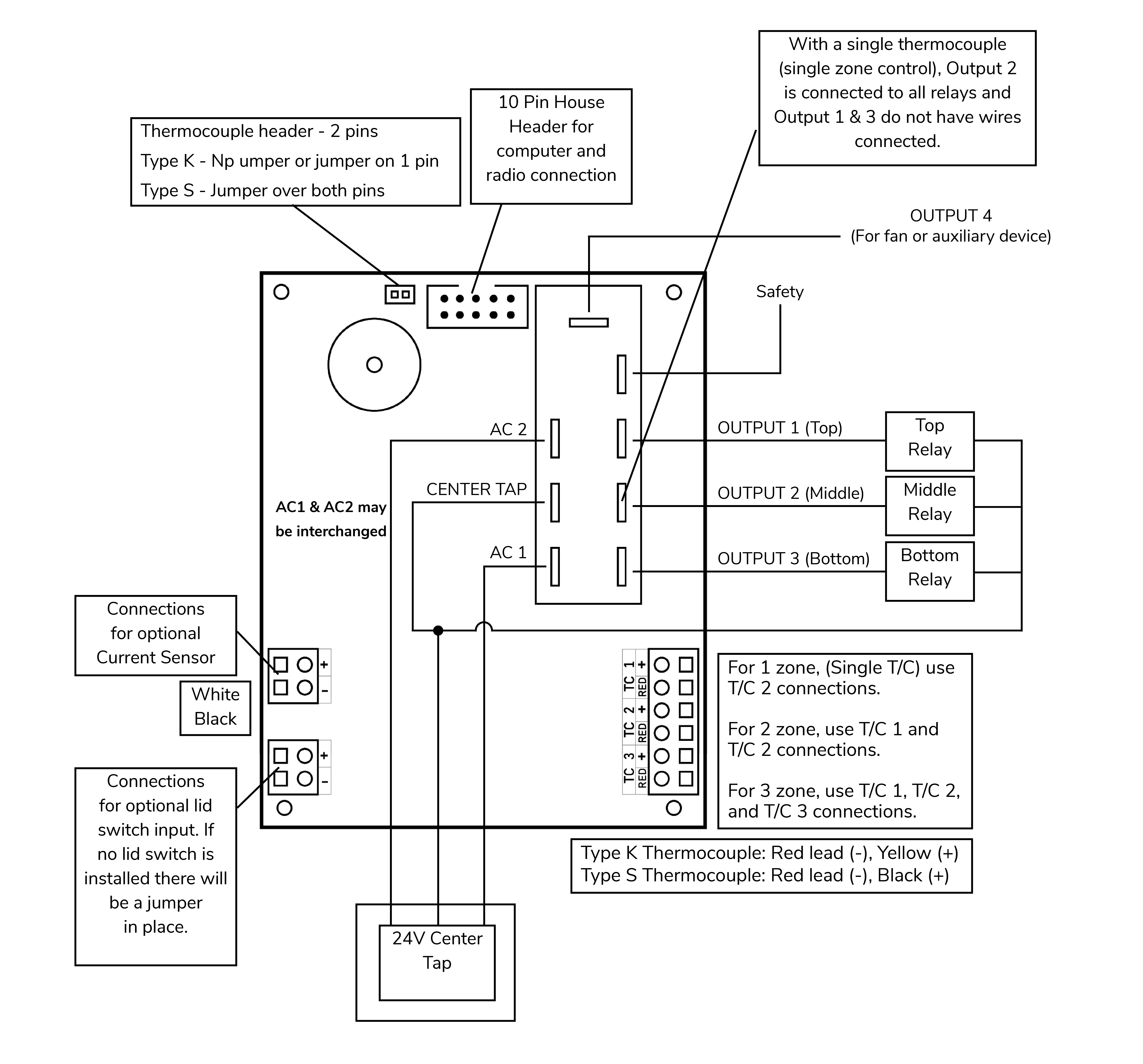
On the Genesis 2.0, the input T/C 2 is used when it is programmed for single zone control. All three outputs work in unison so there are two alternatives for connecting the output. All relays can be connected to output 2 or one relay could be connected to each output. The first method allows direct replacement of the current single zone controller without changing wiring. The second method would allow an easy upgrade to a multi-zone kiln in the future by just adding thermocouples and reprogramming the number of T/C’s. The second method also allows for better use of the diagnostic routines. On the Genesis Mini LT1120, there is only one thermocouple input on the controller
3-ZONE (NUMBER OF THERMOCOUPLES IS THREE) – Genesis 2.0 Only**
T/C 1 is the top thermocouple, T/C 2 is the middle, and T/C3 is the bottom. Likewise, output 1 drives the top relay, output 2 the middle, and output 3 the bottom. For taller kilns, output 2 can control several middle sections.
2-ZONE (NUMBER OF THERMOCOUPLES IS TWO) - Genesis 2.0 Only**
When two thermocouples are selected, use inputs T/C1 and T/C2 and outputs 1 and 2.

See https://www.youtube.com/video/ucB50zDQ-74
Appendix G: Technical Information
Power Supply
The Genesis 2.0 board requires a 24V center-tap transformer. It connects to the board’s bottom three quick connects, labeled AC1, CENTER TAP, and AC2. The VA rating of the transformer is dependent on the electrical load of the board and relays. The board requires approximately 8 0mA at 12V DC and a relay typically requires approximately 140mA at 12V DC. Therefore, a three-relay system will require a transformer with a minimum rating of 6VA (500mA X 12V DC = 6 VA).
The Genesis Mini LT1120 board requires a 24V center-tap transformer. It connects to the board’s 5 pin friction lock connector or to the left three quick connects, labeled AC1, CENTER TAP, and AC2 if the adapter board is installed. The VA rating of the transformer is dependent on the electrical load of the board and relays. The board requires approximately 80mA at 12V DC and a relay typically requires approximately 140mA at 12V DC.
Outputs
The Genesis 2.0 board has five 12V DC outputs. Four outputs are given power by a safety transistor, outputs 1, 2, 3, and safety. The safety transistor is capacitor coupled to the microprocessor so it only powers the output transistors when the microprocessor is operating correctly. Outputs 1, 2, and 3 respond to their respective thermocouple inputs. All outputs are capable of driving a 500mA 12 V DC load. Output 4 is an extra output that can be programmed to run a fan, alarm, or extra kiln section. The maximum combined output of all outputs is 1 Amp. The safety output powers on at the beginning of a firing and off at the end of the firing. It is used to drive a safety relay that sends line power to the switching relays on outputs 1, 2, and 3. When using the optional current sensor, wiring one section to each output will give an Amp reading per section for better diagnostics. See Configuration in the controllers Menu for details on the output 4 options.
The Genesis Mini LT1120 board has three 12V DC outputs. Two outputs are given power by a safety transistor, outputs 1 and safety. The safety transistor is capacitor coupled to the microprocessor so it only powers the output transistors when the microprocessor is operating correctly. All outputs are capable of driving a 500mA 12 V DC load. The maximum combined output of all outputs is 1 Amp. The safety output powers on at the beginning of a firing and off at the end of the firing. It is used to drive a safety relay that sends line power to the switching relays on output 1. When using the optional current sensor, wiring one section to each output will give an Amp reading per section for better diagnostics. See Configuration in the controllers Menu for details on the output 4 options.
Specifications
THERMOCOUPLE
TYPE K, S, and R (MAXIMUM RESISTANCE 100 OHMS)
ACCURACY
+/- 10˚F
COLD JUNCTION COMPENSATION
ELECTRONIC
POWER INPUT
24V CENTER-TAP TRANSFORMER
OUTPUTS 1, 2, 3, 4, AND SAFETY
500 mA AT 12V; FIVE 12V RELAYS WITH 80 OHM COIL
OPERATING TEMPERATURE RANGE
0°F TO 125°F OR 0°C TO 52°C
Full Diagnostic Routine
The full diagnostic routine checks all the output voltages, the amperage or current draw of each section of the kiln, as well as the no load and full load kiln voltages. The amperage or current draw is used to measure the current draw of each section of the kiln. The diagnostic routines can only control each section separately if the outputs are wired for zone control. When checking the output voltages, the controller will turn on each section, starting with the top, for a few seconds. This allows checking to see if all elements are heating. The kiln voltages during load and without load are also measured. This helps to diagnose firing problems when the kiln is not able to reach a programmed temperature. First, it will read the voltages with the elements off, then the elements will come on momentarily and read the voltages again. To run a full diagnostics routine, follow these steps:
- Press the “MENU” button.
- Press the “2-Diagnostics” button.
- Press the “2-Run Manual Diag.” button and the controller will begin the diagnostics routine.
- The controller will flash to the home screen and “CHK ALL” will be displayed across the firing banner. When the test is complete, it will return to IDLE.
- To view the results, press the “MENU” button.
- Press the “1-Data Menu” button.
- Scroll down to “5-Last Manual Diag.” and select it.
- Use the scroll bar to observe the results. You can use the Factory Diagnostics for comparison with your results. When you are finished press the “BACK” button.
- To return to the Home Screen, press “HOME”.
Voltage Calibration
To display voltage using the Genesis controller, a calibration must be done. Before calibration, make sure the relays and elements are connected. To run the voltage calibration follow these steps:
- Press the “MENU” button
- Scroll down to the “6-Factory Config” button and select it.
- Type in the sequence “4”, “4”, “0”, and press the “SAVE” button.
- The screen will read, “Are you sure you want to calibrate the voltages?” If you are ready, press the “START” button to begin or “CANCEL” to return to the menu.
- After the “START” button has been pushed you’ll be asked to enter the no load voltage. The No Load voltage will need to be measured and entered into the controller. Min: 0 Max: 999.
- Once you’ve typed in the No Load voltage, press the “SAVE” button and the screen will change to the Full Load voltage screen, and the power to the elements will be turned on.
- Measure the Full Load voltage and enter the value into the controller and press the “SAVE” button.
- The screen will read Voltage calibration is complete. Press the “HOME” button to return to the home screen.
Appendix H: Genesis Connection Diagram
Appendix I: Genesis Mini Connection Diagram