
REV: 3/15/2025
See this link for Basic Electrical Troubleshooting for Kilns
TABLE OF CONTENTS
ELECTRICAL BASICS
ELECTRICAL SAFETY
Electricity is a wonderful utility but can be dangerous if not approached carefully. There are three basic hazards that cause injury or death – shock, arc-flash, and arc-blast. It is important to remember that even a small amount of current passing through the chest can cause death. Most deaths occurring for circuits of less than 600 volts happen when people are working on “hot,” energized equipment – PLEASE DISCONNECT AND LOCK OUT ALL ELECTRICAL POWER BEFORE ATTEMPTING KILN REPAIRS!
ELECTRICAL HAZARDS
SHOCK
An electrical shock is a current that passes through the human body. Any electrical current flows through the path of least resistance towards ground; if an external voltage contacts a human body, e.g. by touching a live wire with the hand, the voltage will try to find a ground, and a current will develop that flows through the body’s nervous system or vascular system, and exit through the closest part of the body to ground (e.g., the other hand which may be touching a metal pipe.) Nerve shock disrupts the body’s normal electrical functions, and can stop the heart or the lungs, or both, causing severe injury or death.
ARC-FLASH
An arc flash is an extremely high-temperature conductive mixture of plasma and gases, which causes very serious burns when it comes into contact with the body, and can ignite flammable clothing. Arc temperatures can reach up to 35,000°F!
ARC-BLAST
Arc-blast is a pressure wave resulting from arcing, which can carry molten metal fragments and plasma gasses at very high speeds and distances. This can not only carry very hot shrapnel to injure a person but can actually be strong enough to destroy structures or knock workers off ladders.
SAFETY PRINCIPLES
- Be safe! Make sure any equipment that is being installed or serviced is disconnected from all sources of power. In industry, it is important to have ‘Lockout and tag out procedures in place to make sure that power stays disconnected while people are servicing equipment. It is just as important in residential and commercial sites – DO NOT WORK ON LIVE EQUIPMENT UNLESS ABSOLUTELY NECESSARY!
- Use the right tools for the job – do not improvise. For instance, use a proper fuse puller; don’t use a screwdriver to pry out that open fuse.
- Protect the person; use proper gloves, shoes, and clothing. In industry, it is recommended to wear safety goggles or face shields to prevent arc-flash or arc-blast injuries. Wear rubber-soled shoes.
- Make sure the environment around the equipment being serviced is safe. For instance, when working around electricity, it is always very dangerous for the floor to be wet. Make sure there is adequate space to work safely.
- Be aware that current flow across your chest can be fatal. If possible, use only one hand to manipulate test leads when conducting any necessary measurements on live equipment. Use a clamp for one lead, and use one hand to guide the other test lead. Keep the other hand as far as possible from the live circuit components.
INSTRUMENTS COMMONLY USED TO MEASURE ELECTRICITY
An electrician or technician charged with the responsibility of maintaining or installing devices that use electricity needs to have a number of tools close at hand. In addition to hand and power tools, these should include instruments that can be used to diagnose electrical trouble. CAUTION! Be sure to follow all instructions and safety procedures that are included in the instrument manufacturer’s package.
TEST LAMP
This consists of a rubber-insulated socket with an incandescent light bulb (rated for the highest voltage to which it might be subjected), to which is attached (2) two probes for attaching to the power source being diagnosed. At least one of these probes should be fitted with a clamp so that it can be attached to one of the power source leads, while the other is manipulated (with one hand only). This is used for very rough diagnostics on open fuses, interior lighting, motor, and resistance circuits.
CLAMP-ON AMMETER
These are very convenient test instruments, used for determining the number of amperes flowing in a cable. Only one (1) cable can be measured at a time, and the cable can either be bare or insulated. The cable to be measured is (carefully) segregated from other current-carrying cables, and shifted enough so that the jaws of the clamp-on ammeter can be opened, slipped around the cable, and then closed. As soon as the jaws close, a clear and accurate reading is registered on the scale. The jaws are insulated, and the Bakelite handle and shield protect the technician from shock. The meter is operated by the magnetic field set up by the current.
OHMMETER
This is used to measure the resistance of a circuit. Usually, this is found in combination with a voltmeter, and milliammeter, in a device known as a MULTIMETER (see below). Some Ohmmeters are very precise, for laboratory use.
CAUTION! Never connect an ohmmeter to a circuit until the circuit has been disconnected from the power source. The ohmmeter has its own internal power supply, and connecting it to another power source can cause serious damage.
VOLTMETER
Voltmeters are used to measure the voltage that exists in a circuit. Typically, the technician selects an appropriate scale (0-150 volts, 0-250 volts, 0-500 volts, etc.), and then clamps one of the probes to one of the hot lines. The other probe is then carefully put in contact with the other hot line, and the meter registers the voltage. Voltmeters have very high resistance, in the range of 15,000 W, so that very little current flows in the voltmeter circuit; just enough to cause the voltmeter to indicate voltage across its scale.
DIGITAL MULTIMETER
This is probably the most useful instrument in an electrician’s toolbox. It is a combination ohmmeter, voltmeter, and milliammeter. A good meter measures ohms, AC volts, DC volts, and AC and DC amperes (at least up to 300 milliamperes), as well as provide a continuity tester (audible) that measures continuity within a component (such as a fuse). Typically the multimeter has different sockets for the probes to connect to. One probe goes to Common, and the other is connected either to Volts/Ohms or to Amps. (Click here to see how to use a multimeter)
CAUTION! Never connect the multimeter “Hot” probe to the Amps socket when measuring Volts. There is an internal power source that supplies its own voltage when making Amperage measurements; applying an external voltage to this internal circuit can cause serious damage. Most good multimeters have an internal fuse to prevent the most serious damage; however, it is still a nuisance to replace fuses.
After connecting the probes to the appropriate sockets, the technician selects the type of measurement being made. The correct scale may have to be selected also if the multimeter is not “autoscaling.” One probe should then be clamped to one part of the circuit being measured for safety, and then the other carefully put into contact with the other side. The meter displays the value, and usually the unit of measurement.
SOME BASIC ELECTRICAL THEORY
Simply put, electricity is nothing more than the flow of electrons through a conductor. Some understanding of the structure of matter is necessary in order to understand the fundamental nature of electricity.
ATOMS, PROTONS, NEUTRONS, AND ELECTRONS
Matter is anything that occupies space and has mass. Some examples are water, glass, wood, and steel. All matter consists of molecules, which are extremely small particles. These particles, even though tiny, still retain some chemical properties. Molecules can be further divided, into atoms, or elements. Dividing molecules into atoms creates a chemical change; i.e., water molecules undergo a chemical transition to become 2 parts of hydrogen and 1 part of oxygen (2 hydrogen atoms and 1 oxygen atom.)
Atoms, or elements, are known as the building blocks of matter. Singly, or in combination, atoms are the materials that constitute all matter. Some examples of elements are iron, hydrogen, and carbon. There are approximately 115 known elements. The structure of each atom can be roughly compared to a star and its planetary system. Like the star, the nucleus of an atom is at the center. Surrounding the nucleus are tiny electrons, which have a negative charge, the quantity depending on the element. The nucleus consists of protons, which have a positive charge, and neutrons, which carry no charge.
The simplest atom is the hydrogen atom, which has a single proton (+) in the nucleus, and a single electron (-) orbiting the nucleus. A more complex atom is the copper atom, which has 29 protons (+) and 35 neutrons (no charge) in the nucleus, and 29 electrons (-) orbiting the nucleus. In their natural state atoms contain an equal number of protons and electrons, and have a neutral charge. The electrons are arranged in several layers, or rings, around the nucleus, and these rings are called shells. The number of the shell determines the maximum number of electrons that can exist in a shell; the first shell is closest to the nucleus, and the numbers increase consecutively the further away they are from the nucleus. The maximum number of electrons that can exist in a shell is as follows: 2 electrons in the first shell, 8 in the second, 18 in the third, 32 in the fourth, 18 each in the fifth and sixth, and 2 in the seventh.
The ability of a material to let go of its electrons is called conductivity. For various reasons, materials that are good conductors have from 1 to 4 electrons in their outermost shells. For example, the two most common conductors used for electrical wiring are copper, which has 1 electron in its last shell, and aluminum, which has 3. Atoms with 5, 6, or 7 electrons in their outermost shells are called nonmetals and are poor conductors; atoms with 8 electrons are insulators.
STATIC ELECTRICITY
Static electricity is an electric charge that builds up in an object. Friction can build an electric charge up in an object. We are all familiar with rubbing our stocking feet on a carpet, building up a charge in our bodies, and then touching an uncharged (neutral) object to release the charge (sometimes with an audible crack and a visible spark.) This charge consists of an excess number of electrons relative to the protons in the object, and this excess builds up from rubbing against a different material that releases its electrons more quickly than the object being charged.
This charge can accumulate in an object if is not discharged. For instance, rubbing a glass rod with silk causes electrons to flow from the silk to the glass rod, and thus builds up a charge in both the silk and the glass rod. Also, rubbing a rubber rod with fur causes electrons to flow from the fur to the rubber rod. If the glass rod is brought in proximity to another similarly charged glass rod, they repel each other. Also, two rubber rods repel each other. But if a glass rod is brought close to a rubber rod, they attract each other, because they have opposite charges. The storage of this charge is called “electricity at rest”, or static electricity.
There are two basic rules for electrical charges:
- Like charges repel, and opposite charges attract.
- The strength of this repulsion or attraction is directly proportional to the strength of the electrical charge and inversely proportional to the square of the distance between the charged objects.
ELECTRICITY IN MOTION
Most electricity that we use to do work is in the form of an electric current, which is electricity in motion. Electrons move through a conductor by passing from one atom to another. A material that has some electrons that are free to flow in this manner are called conductors; materials that do not have free electrons are insulators. Rubber and ceramics are typically good insulators; metals are typically good conductors. If a copper wire is connected between two bodies of opposite charge, electrons will flow freely through the wire, attempting to balance the charge.
There are two common types of electric currents, DC or direct current, and AC or alternating current. DC is a current that always flows in the same direction. Common examples are automobile circuits that are powered by batteries, and flashlights, also powered by batteries. A battery is a device that uses chemicals to create an unbalanced charge between its terminals and thus causes a direct current to flow from a (+) terminal to a (-) terminal. This DC electricity can be harnessed to perform such tasks as lighting, playing music on a radio, etc.
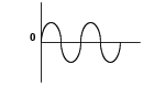
AC electricity is typical in households and businesses. In this form of current, the direction of electron flow is reversed at regular intervals by the electrical generator that produces the AC. The voltage (level or pressure of electricity) as it is generated increases from zero to a maximum value in one direction, then reverses down to zero, and continues to a maximum value in the other direction, and increases back to zero in the original direction, and so on. If plotted on a graph, the curve appears like the one in the accompanying figure.
Electricity has four basic characteristics: Voltage (Pressure), Amperes (Flow), Ohms (Resistance), and Watts (Power). The flow of electrons through a circuit can (and commonly is) be compared to the flow of water through a pipe. The rate of flow of water is analogous to Amperes, Ohms to pipe diameter, water pressure to Voltage, and Watts to gallons of water. We can talk about each of these individually, and then discuss specific types of electrical circuits such as Series Circuits and Parallel Circuits.
ELECTRIC CURRENT (AMPERE)
The basic unit of electricity is the coulomb and is equal to approximately 628 x 1016 electrons. Since the rate of flow of electricity is what is typically of interest, rather than the total quantity of electricity, the coulomb is not generally of practical use, except as the fundamental quantity on which other electrical characteristics are based.
An Ampere represents the flow of 1 Coulomb per second. The relationship between the Ampere and the Coulomb can be represented mathematically as:
Q = It
Where Q = quantity of coulombs (C)
I = current, in amperes (A)
t = time, in seconds.
Amperage would be analogous to the rate in gallons of water flow through a pipe.
ELECTRICAL RESISTANCE (OHMS)
All materials have some opposition to current flow, and this opposition results in some of the electrical energy being converted to heat. This conversion is in accordance with the formula, W=I2R, where W is Watts, I = Intensity of electrical current (Amperes), and R is resistance in Ohms. See the section on OHM’s Law, below. Electrical resistance is analogous to the restriction of the pipe diameter to the flow of water.
As we saw above, different materials have different quantities of free electrons. The opposition is caused by the type of material that the current is attempting to pass through, as well as by friction caused by the motion of electrons. This friction is affected by the diameter of the wire, as well as by the length of the wire.
The opposition of the flow of electrons is called resistance. The unit of resistance measurement is the ohm (W). One (1) Ohm is the opposition to electrical flow that results in electrical energy being converted into heat at the rate of one (1) Watt per Ampere of effective current. The instrument that is used to measure resistance is the ohmmeter.
Some materials that are good conductors: copper, silver, gold
Some materials that are good insulators: rubber, glass, bakelite, wood, porcelain (especially electrical grade porcelain)
Other materials are conductors despite having some insulating properties; these are called resistors. Examples of resistors are alloys such as iron-aluminum chrome, and nickel-chrome, which are used as heating elements in kilns, furnaces, and ovens.
ELECTROMOTIVE FORCE (VOLTAGE)
A volt is a unit of EMF, or electromotive force, and is internationally defined as that emf which will establish a current of 1 Ampere through a resistance of 1 Ohm (Ω). Voltage is analogous to water pressure and is the force that pushes the water through a pipe.
Referring to the previous discussion concerning atoms, electrons, and matter, it can be said that all matter consists of electricity. In strict terms, electricity cannot be generated; it can only be made to move and therefore transmit power from one source to another. Electrical energy (as opposed to electricity) can and is generated (or converted) from other forms of energy. There are several common methods of generating electrical energy, some of which are mechanical induction, chemical, thermoelectric, and friction. This is how voltage is supplied in most common applications.
For instance, mechanical induction is the method which AC produces voltage. An AC generator produces a voltage first in one direction, and then another. This is done by rotating a large coil of wire through a magnetic field (or vice versa). As the wire coil moves through the magnetic field, a voltage develops.
ELECTRICAL POWER (WATTS)
Strictly speaking, power is the time rate for doing work. The faster work is done, the greater the power that will be required to do it. Horsepower is the basic unit measurement of power and is defined as 33,000 ft-lb/min. The formula is:
hp = L x W = ft-lb / min
33,000 x t 33,000
where hp = horsepower, L = distance in feet through which W is raised or overcome, W = weight in pounds of the object being moved (or the push or pull in pounds of force being exerted), and t is time in minutes required to move weight W through distance L.
Electric power is the rate of doing electrical work. Its unit is the watt, or kilowatt, which is 1000 watts. One (1) watt is developed when (1) ampere is maintained through resistance by an emf of (1) volt. The relationship between kW and hp is:
(1) hp = 746 W
Electrical energy is expressed in terms of kilowatt-hours (kWh), and (1) kWh is the energy expended if work is done at a rate of (1) kW for 1 hour.
OHM’S LAW
Ohm’s law can be applied to an entire circuit, or to any portion of it. This may be stated:
- The total current flowing in a circuit is equal to the total voltage applied to the circuit divided by the total resistance of the circuit.
- The current flowing in any part of a circuit is equal to the voltage across that part of the circuit divided by the resistance of that part of the circuit.
ELECTRIC CIRCUITS
An electric circuit is a path over which electrons flow. The two basic kinds of circuits are series and parallel. A combination (or series-parallel) circuit has elements of both basic kinds of circuits, where some components are connected in series and others are joined in parallel.
All circuits are composed of the same basic components:
- A voltage source
- (1) Or more electrical loads
- (1) Or more control devices (switches, relays, etc.)
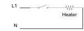
A simple circuit as illustrated consists of a voltage source (L1 and N), a SPST switch, and a heater.
SERIES CIRCUITS
A circuit that only has one path over which current can flow is a series circuit. A break in any part of a series circuit stops current flow. All components in a series circuit see the same amount of current; therefore, each component must be capable of carrying that number of amperes.
RULES FOR SERIES CIRCUITS
- The value of a current flowing in a series circuit is the same through all parts of the circuit.
- The total voltage of a series circuit is equal to the sum of the voltages across each part of the circuit.
- The total resistance of a series circuit is equal to the sum of the resistances across each part of the circuit.
Line voltage is divided across each component in a series circuit in proportion to the component resistance values. Referring to the schematic below, the total resistance is (25Ω + 30Ω = 55Ω). Voltage measured between points A and B is (240 Volts x 25Ω / 55Ω) = 109 Volts.
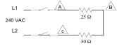
If there were (2) resistances whose values were equal, the voltage would be divided equally in half, and would measure 120 Volts.
PARALLEL CIRCUITS
A circuit that has two current paths is a parallel circuit. Each component is connected to line voltage, and current still flows through part of the circuit if one component fails. Each component must be capable of withstanding line voltage. The number of amperes varies according to the resistance of the component.
The more circuit paths, the less opposition to the flow of electrons. Total circuit resistance decreases when more paths are added.
RULES FOR PARALLEL CIRCUITS
- The total current supplied to a parallel circuit is equal to the sum of the currents through the branches.
- The voltage across any branch of a parallel circuit is equal to the supply voltage.
- The total resistance of a parallel circuit is always less than the resistance of any of the branches.
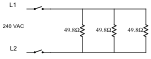
The following parallel circuit is typical of the DaVinci and J2900 kiln rings; there are (3) elements per ring, connected in parallel. In this example, each element has a resistance of 49.8Ω; at 240 VAC, each element develops (240 VAC / 49.8Ω) = 4.82 Amperes. The total circuit amperes, then, is 4.82 + 4.82 + 4.82 = 14.46 Amperes.
SERIES/PARALLEL or COMBINATION CIRCUITS
Certain circumstances require the use of Series/Parallel, or Combination, circuits, in which series and parallel circuits are combined. In some front-loading industrial furnaces these circuits are used to combine, for instance, sidewall heating elements and backwall heating elements (often shorter than sidewall) in a branch circuit that is controlled by a power relay.
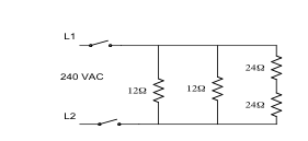
In the above example, the total resistance can be found by first dealing with each branch circuit individually. Starting from the right, this circuit is a series circuit; add the (24Ω + 24Ω = 48Ω). The other two circuits are parallel and are equal in value (12Ω each); therefore, the resistance value of these two circuits is equal to (12Ω/2 = 6Ω). Drawing an equivalent circuit with (2) parallel circuits, one of 6Ω and one of 48Ω, looks like the following:
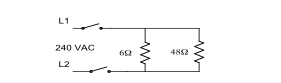
Solving for this circuit: Rt = (6Ω * 48Ω) / (6Ω + 48Ω) = 5.33Ω.
The total resistance is lower than that for any of the branch circuits.
NOTE FOR OUR CUSTOMERS: Generally speaking the decision about how to wire a particular kiln is based on maximizing element life and other factors. Occasionally we will switch from Parallel to Series or vice versa based on a particular experience.
CONDUCTORS AND WIRING METHODS
CONDUCTORS
A conductor is any material that offers little opposition (resistance) to the flow of an electric current. Most familiar conductors are either copper or aluminum wire, covered in various forms of insulation. The size of conductors varies greatly with the amount of current they carry, and their intended use and environment. Because most conductors are relatively small in diameter, the unit called circular mils has been selected to measure the size of conductors. One mil is equal to one-thousandth of an inch (.001 inch). One circular mil is the area of a circle one mil in diameter. The symbol for mil is m, and for circular mil is cm (not to be confused with the metric symbols for meter and centimeter). The formula A = m2 can be used to determine the circular mil area of the wire, where
A = area, in circular mils (cm)
M = diameter, in mils (m)
In the U.S., a special scale has been developed for the most common wire sizes. This is the American Wire Gauge, or AWG. The following table is based on the 1999 National Electric Code®, Tables 310-16 and 310-18. This is the allowable ampacities of Insulated Conductors, (3) current-carrying conductors in a raceway or cable, and is based on an ambient temperature of 86°F.
| Size (AWG/kcmil) | 60°C (140°F) | 75°C (167°F) | 90°C (194°F) |
|---|---|---|---|
| 14 | 20 | 20 | 25 |
| 12 | 25 | 25 | 30 |
| 10 | 30 | 35 | 40 |
| 8 | 40 | 50 | 55 |
| 6 | 55 | 65 | 75 |
| 4 | 70 | 85 | 95 |
| 3 | 85 | 100 | 110 |
| 2 | 95 | 115 | 130 |
| 1 | 110 | 130 | 150 |
| 1/0 | 125 | 150 | 170 |
| 2/0 | 145 | 175 | 195 |
| 3/0 | 165 | 200 | 225 |
| 4/0 | 195 | 230 | 260 |
| 250 | 215 | 255 | 290 |
| 300 | 240 | 285 | 320 |
| 350 | 260 | 310 | 350 |
| 400 | 280 | 335 | 380 |
| 500 | 320 | 380 | 430 |
| 600 | 355 | 420 | 475 |
| 700 | 385 | 460 | 520 |
| 750 | 400 | 475 | 535 |
| 800 | 410 | 490 | 555 |
| 900 | 435 | 520 | 585 |
| 1000 | 455 | 545 | 615 |
| 1250 | 495 | 590 | 665 |
| 1500 | 520 | 625 | 705 |
| 1750 | 545 | 650 | 735 |
| 2000 | 560 | 665 | 750 |
The recommended wire gauge for connecting our kilns are based on the use of 75 Deg C wire. There are correction factors that must be taken into account for such variables as ambient temperature (less ampacity as the ambient temperature rises) and number of conductors in a cable or raceway; these factors are fully detailed in the National Electrical Code®.
INSULATION TYPES
Various types of plastic are by far the most common insulations used on conductors. For general-purpose building wire, types TW, THW, and THWN are used more than any other type. Other types have been developed for machine tools (MTW) where the conductors are likely to encounter harsh cutting fluids. Likewise, for high ambient temperatures, several types of insulation have been developed, including the type favored by L&L, which is SEWF. This is a high-temperature silicon rubber-based insulation.
VOLTAGE DROP - 220V versus 230V versus 240V
Where long wire runs are experienced between the power supply and the point of connection, it is possible for the measured voltage at the point of connection to be lower than the measured voltage at the power supply. This is caused by transmission losses through the wires, and can also be aggravated by having excessive connections from one transformer in a neighborhood power grid, or within a single facility. For instance, many of the U.S. electrical utilities supply 240V from the transformer, but the measured voltage coming into a residence may be 230V or even 220V. For resistance heating devices such as electric kilns (and ovens or ranges) this lower voltage can result in slightly slower firings than would be the case if the actual voltage were 240V - but in practice, this does not usually cause problems.
To prevent or ameliorate this voltage drop, larger-size conductors can be used for long runs. One rule of thumb is to use one size larger wire for every 50 feet of run from the power supply to the connection point; the electrician should be able to make this determination on-site.
Also, using a wire material of low resistivity can keep voltage drop to acceptable levels. Aluminum wire has a resistivity (Ohms – circular mil per foot) of 17.0; copper has a resistivity of 10.4. Therefore, the resistivity of copper is 10.4/17.0 = 0.61, or 61% of aluminum’s resistivity. L&L recommends using only copper wire for connection from a kiln to any power supply; in addition to the resistivity difference, there are differences in the rate of corrosion that are aggravated by the high ambient temperatures common at the kiln connection point.
WHY 230V AND 460V RATINGS?
Undervoltage conditions can affect the operation and service life of motors; these are usually rated at ±10% of nameplate voltage - thus the common rating of 230V or 460V for motors, which can usually be safely operated at the lower voltages sometimes found at service connection points. In many industrial plants the most common equipment is operated by electric motors, and it is common to refer to the actual power supply as 230V or 460V even though the normal supply voltage from the utility is 240V or 480V.
FUSES AND CIRCUIT BREAKERS
Fuses and circuit breakers are overcurrent devices designed to protect electrical circuit components. If a circuit develops too many amperes, they are designed to open, interrupting the flow of current in the circuit. Fuses self-destruct when they sense an overload in the circuit. Circuit breakers are commonly used in new construction; they trip (turn off the power) when they sense an overload and can be reset (turned back on) when the circuit is returned to normal.
Circuit breakers are more convenient because of this feature. However, they can cause nuisance tripping and ruin kiln firings when they trip part way through a firing. This is because most circuit breakers are activated thermally; if the circuit breaker temperature rises above a preset level, a bimetallic element inside the circuit breaker opens, and the power is turned off. This works well most of the time; however, over time the bimetallic element becomes weaker because resistance heating circuits are at their rated load longer than other types of electrical loads such as motors. Eventually, the circuit breaker becomes too weak to hold itself closed over a long enough time to finish a kiln firing, unless the circuit is drastically oversized to compensate for this gradual aging process.
There are many different types of fuses, including dual-element time delay, one-time, sub-cycle, etc. Most of these designations relate to how quickly a fuse will “blow” in response to an overload, and these types of fuses have been developed to protect not only the circuits but also varying types of equipment. For instance, SCRs (silicon-controlled rectifiers) need to be protected from voltage spikes which can occur within 1/60 of a second and destroy the device - these are usually protected by ‘semiconductor’ fuses which are very fast acting, current limiting, and have no time delay.
Another consideration in selecting fuses is the interrupting capacity in amperes - in other words, how big a short circuit can be opened by the fuse. In large industrial plants, this can be an important factor, because if enough power is available it would be possible that a short circuit would allow too many amperes to flow into a circuit for a general-purpose type fuse to interrupt - which could potentially cause an electrical fire. Most residences and small commercial shops do not have enough power available before the main circuit protector (usually a 200 amp circuit breaker) would open, and a small interrupting rating (10,000 Amps or 50,000 Amps) is enough.
For protecting kiln circuits, ‘one-time’ general-purpose type fuses should be used. These are inexpensive, have no appreciable time delay, and are available in a large variety of sizes. They are also widely and easily available and are made by several large fuse manufacturers. Different manufacturers have different designations for their ‘one-time’ fuses; some of the more common ones are:
|
MANUFACTURER |
MAX RATED VOLTS |
INTERRUPT RATING |
FUSE DESIGNATION |
|
LITTELFUSE |
250 VOLTS |
50,000 AMPS |
NLN |
|
BUSSMAN |
250 VOLTS |
50,000 AMPS |
NON |
|
GOULD SHAWMUT |
250 VOLTS |
50,000 AMPS |
OT |
|
LITTELFUSE |
600 VOLTS |
50,000 AMPS |
NLS |
|
BUSSMAN |
600 VOLTS |
50,000 AMPS |
NOS |
|
GOULD SHAWMUT |
600 VOLTS |
50,000 AMPS |
OTS |
All overcurrent devices must be sized to carry 125% of the continuous ampere load; for instance, a 240 V/1 Phase Model J230 kiln is rated at 44 amperes. The overcurrent device must be rated at 125%, or (1.25 x 44 = 55 Amperes) minimum. The closest commercially available device is rated for 60 Amperes; a 50-Ampere device is not adequate.
ELECTRICAL DISTRIBUTION
Electrical distribution from the electric company’s power generation plant is generally by high voltage 3 phase lines. These can be branched to sub-stations that transform the as-generated power to a lower (but still relatively high) voltage for further distribution. Ultimately, for each service (whether a single industrial plant, shops in a shopping center, or houses in a residential neighborhood) this supply is connected to a transformer, which changes the high voltage supply to line voltages ranging from 208V to 480V.
SINGLE PHASE SERVICES
Most residential services are single-phase, but many of these are distributed from 3 Phase “Wye” transformers. They include two hot legs from the “Wye” plus a grounded neutral, and, of course, a system ground. A true single-phase service comes from a transformer that is connected to only one phase from a sub-station high voltage supply. These can be found in many residential neighborhoods, and sometimes in industrial plants. Usually, the voltage supplied is 240V, with 120V from phase to neutral.
120/240 VOLTS / 1 PHASE
This the most common household power supply found in the U.S. The primary of a single-phase transformer is connected to one phase of the three-phase distribution system. The secondary contains two coils connected in series with a midpoint tap to provide a single-phase, three-wire system. The two ‘hot’ wires, or lines, provide 240 Volts, and either of the ‘hot’ lines to neutral provides 120 Volts. You will sometimes see this expressed as a 110/220. (For purposes of order elements you will still get 240-volt elements when you see 110/220.)
120/208 VOLTS - 1 PHASE
For some commercial facilities and some newer residential supplies, the electrical supply is distributed within a neighborhood power grid, and each supply is 120/208V-1 Phase. Two “hot” legs at 208V, a grounded neutral for (2) 120V circuits, and of course the system ground, comprise the electrical supply. In these cases appliances are rated for 208V-1 Phase, and kilns should be ordered as such.
THREE PHASE SERVICES
“WYE” VERSUS “DELTA” 3-PHASE SYSTEMS
A 3 Phase power supply is classified as “Delta” if the hot legs are connected phase to phase, with a grounded neutral. When diagrammed, the circuit looks like a triangle (therefore the term “Delta”), with the hot legs shown as the three points defining the triangle, and the three power circuits drawn between them. The voltage between the grounded neutral and any one of the hot legs measures ½ of the supplied phase-to-phase voltage. A variation of this can be supplied where two of the phase-to-neutral voltages are measured as ½ the phase-to-phase voltage, and the other is measured at another commonly seen voltage such as 208V. This type of electrical service is usually found in industrial plants, and the phase-to-neutral voltage is not commonly used for electrical circuits.

In a “Wye” power supply the hot legs of the 3-phase system are each connected to a grounded neutral. When diagrammed the circuit looks like the letter “Y” with each of the hot legs shown at one of the outer arms of the “Y” and the grounded neutral at the central junction point. The phase-to-neutral voltage is reduced by the 3-phase factor (Square Root of 3 = 1.73). E.g., for a phase-to‑phase voltage of 208V, divide (208V by 1.73 = )120V circuit voltage. This type of service can be found in industrial plants, commercial sites, and residential areas; phase-to-phase voltages and phase-to-neutral voltages are all commonly used for electrical circuits.

240 VOLTS / 3 PHASE
Most 240 Volts / 3-Phase systems are provided as Delta, with a grounded neutral to supply 120 Volts as a phase-to-neutral voltage. A very common type is 240 VAC Delta, three wires with a grounded center tap on one of the phases “high” leg to obtain 120 Volts between two of the phases to neutral and 208 Volts between the third phase to neutral. Another common service is similar but is 120 volts to neutral on all three phases.
A grounded neutral conductor is also usually included with these types of electric service to obtain lower voltages such as 110-120 or even 208 volts and may be used in many residential or commercial installations to help in distributing the typical 110-120 lighting and outlet circuits. If the loads between the phase-to-neutral circuits are close to being balanced (similar in amperes), the neutral conductor ends up carrying little or no amperes - because the three phases are generated 120° apart in time, and therefore cancel each other out when connected together on the neutral (hence the nomenclature “neutral.”)
208 VOLTS / 3 PHASE
Many schools, institutions, and commercial or light industrial facilities are wired with 120/208 Volts, 3 Phase, Wye connection electrical power supply. This type of supply is an efficient method of supplying heavy 120V loads and is also increasingly being used in residential services for that reason.
The “Wye” connection works by putting an electrical circuit from one “hot” leg of the 3-phase system to a grounded neutral. This reduces the effective voltage by the 3-phase factor (Square Root of 3 = 1.73). Therefore, with a phase-to-phase voltage of 208V, divide the 208V by 1.73 = 120V.
In non-residential use, most facilities are supplied with the full 120/208V system, and the distribution is done inside the facility for the 120V circuits and for the 208V-3Phase circuits. It is generally most economical to use the 3 Phase supply for equipment; therefore, it is recommended that 208 Volt/3 phase kilns be ordered for these facilities. Single-phase kilns can be used; however, they would require heavier gauge wire for hook up and would tend to unbalance the distribution system inside the facility.
480 VOLTS / 3 PHASE – DELTA AND ‘WYE’
Many industrial facilities are equipped with 480V services, which are very efficient for supplying equipment with high power requirements. These can be found as either Delta or “Wye.” In either case, the line-to-line voltage is 480 Volts. When supplied as a “Wye” system, the phase-to-neutral voltage is 277 Volts, which is very efficient for supplying lighting loads. In buildings where this service is found, a step-down transformer is used to supply 208-120 Volts/ 3-Phase “Wye”, for 120 Volt loads. This makes for a versatile power supply but can cause confusion as to what voltage is available for equipment. Be sure to measure line-to-line voltages on all three phases so that the type of voltage available can be determined for certain. It is a good idea to talk to the building superintendent or electrician when ordering kilns or any other kind of electrical equipment because they would know for sure which of the power supplies would be available. It is costly to convert to a different voltage than the one ordered after the fact.
ELECTRICAL CONNECTION NOTES FOR L&L KILNS
208, 220, AND 240 VOLT SINGLE-PHASE CONNECTION
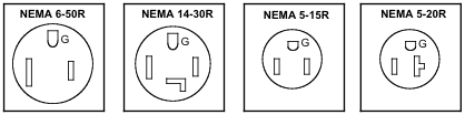
Most standard L&L kilns are supplied for 208, 220, or 240-volt, single-phase service. Connecting these kilns to a power supply is relatively straightforward. There are (2) hot lines and ground. Single-phase L&L Kilns do not use a neutral wire to power any of the circuits; all circuits are based on line voltage. For single-phase kilns rated for 44 Amperes and less, a NEMA 6-50P cordset is provided. The power supply must feed a NEMA 6-50R receptacle. The exception to this is the Model GS1714, which uses a 30 Amp NEMA 14-30P cordset, which is the typical dryer cord found in most parts of the U.S. All single-phase L&L Kilns rated for more than 48 Amperes must be wired directly; these are no cordsets provided.
1-PHASE, 30 AMPERE “DRYER CIRCUIT” POWER SUPPLY FOR JUPITER KILNS
L&L supplies single-phase JUPITER Kilns with a specially configured, high-temperature NEMA 6-50P cordset, even though for some models it would be permissible to use a 30-Amp cordset based on the ampacities involved. These Kilns have been listed to UL499 standards; this listing is dependent on certain specific components that are tested to UL standards under strict guidelines.
Because there are different "standard" dryer outlet configurations, in different jurisdictions and depending on when the outlet was originally installed, there is no set answer to the question of whether you can utilize an existing dryer circuit for a single-phase Jupiter kiln equipped with the NEMA 6-50P plug and cord assembly that L&L uses on these kilns. If a Kiln owner decides to make this change on his/her own, be advised that the UL listing no longer applies because this listing is dependent on certain specific components that are tested to UL standards under strict guidelines. One of the most important of these components is the main power cord, which would necessarily be modified to make this change. UNDER NO CIRCUMSTANCES SHOULD ANYONE EVER SUBSTITUTE AN OFF-THE-SHELF DRYER CORD FOR THE NEMA 6-50P CORD SUPPLIED BY L&L - SUCH OFF-THE-SHELF CORDS ARE NOT RATED FOR THE TEMPERATURES THAT ARE NORMAL AT THE KILN POWER TERMINAL BLOCK.
NEMA CONFIGURATIONS FOR L&L POWER CORD SETS
L&L supplies cord sets for 1-phase Kilns (and some 3-phase kilns), rated for 48 Amperes or less. Most of these are NEMA 6-50P. The 3-Phase plug we use on the Easy-Fire kilns is a 15-50P. The Doll/Test kiln is supplied with either a NEMA 5-15R or 5-20R. Liberty-Belle kilns use a variety of 30 amp cord sets (see the Liberty-Belle Specification sheet for more information).
208, 220, AND 240 VOLT, THREE-PHASE DELTA CONNECTION
ALL STANDARD L&L KILNS SUPPLIED FOR 208 OR 240-VOLT, THREE-PHASE SERVICE MUST BE WIRED IN DELTA, OR PHASE TO PHASE, RATHER THAN PHASE TO NEUTRAL. DELTA means that the electrical load(s) are connected between the “hot” leads, that is, one load is connected between L1 and L2, another is connected between L2 and L3, and the third is connected between L1 and L3.
There is a lot of confusion concerning three-phase services because there are so many different types that are common in the U.S.A. However, when ordering an L&L Kiln for 208 OR 240 Volt, Three-Phase operation, make sure to measure the voltages between all combinations of the Line wires (L1 to L2, L2 to L3, and L3 to L1.) This should be close to either 240 VAC across all three phases, or 208 VAC, with some tolerance (no more than 10%) allowed for voltage drops.
In these Standard L&L Kilns all the heating and control circuits are designed to operate from Line voltage, and there are no circuits that are operated from the possible reduced voltages available from Line to grounded neutral.
480/277 VOLT and 380/220 VOLT, THREE PHASE WYE CONNECTION
There are some exceptions to the above rule: there are some specially designed kilns to operate on 480 VAC/277 VAC, three-phase WYE, in which the heating circuits operate from Line to neutral, and the control circuit is operated from an isolated control transformer. In addition, some kilns for overseas operation are wired for 380 VAC/220 VAC, three-phase WYE, in which both the heating and control circuits are operated from Line to grounded neutral.
OVERSEAS ELECTRICAL DISTRIBUTION
Overseas electrical voltages vary from country to country, and range from 220/380V “Wye” power supply where 220V is a common household voltage, to 240/415V “Wye” where 240V is common, and can go as high as 575 or 600 Volts Delta, which is relatively common in Canada. The lower voltage in “Wye” systems is determined by the “3-Phase factor,” which is the square root of 3 (approximately 1.73). Divide the phase-to-phase line voltage by the 3-phase factor to obtain the phase-to-neutral voltage (e.g., 380 / 1.73 = 220V). L&L Kilns are available for 380/220V – 3 Phase “Wye”, as well as 220V – 1 Phase and 415/240V - 3 Phase "Wye".
ELECTRONICS AND KILN CONTROL
With the advent of Automatic, or ‘Computer-control,” Kilns, Electronics have taken on more importance in the ceramics industry. Electronic Kiln controllers are called upon to control the flow of electricity to the heating elements, in order to achieve a desired time/temperature program. There is a basic feedback loop involved, in which a measurement of temperature is compared by the electronic microprocessor to the desired program which is stored in the memory of the controller. In response to the offset between the measured temperature and the programmed ‘setpoint,’ the controller allows electricity flow to the heating elements.
THERMOELECTRIC EFFECTS
Referring to the discussion in previous sections concerning atoms, it takes a lot of energy to dislodge a proton or a neutron from an atom. But electrons move with the slightest nudge, especially in metals, where a small voltage, a tiny amount of heat, or the impact of a few photons is all it takes. Thermal and electrical energy work together, one enhancing the effects of the other, as several scientists is the 19th century discovered. Three in particular, Thomas J. Seebeck, Jean Peltier, and Sir William Thomson (Lord Kelvin), made some discoveries that are very influential in the heat processing industry today.
In 1821, Seebeck discovered that a pair of wires made from dissimilar metals and joined at both ends would move a magnetic needle if the ends were held at different temperatures. The needle deflection indicates electron flow or current. A further development has been to open one of the ends and expose the joined end to temperature. A very small voltage, which depends on the temperature at the junction and the composition of the two metals, can be detected at the open end, and this is called the Seebeck voltage. This voltage is proportional to the change in temperature; the proportionality constant is known as the Seebeck coefficient. This circuit is known as a thermocouple. The voltages found are very small and measured in units of thousandths of a volt, called millivolts.
Thermocouples are made with various types of dissimilar metals. Automatic L&L Kilns are equipped with a variation of “Type K” thermocouples as standard equipment. These are made with a negative Nickel-Chromium (Chromel®) wire joined to a positive Nickel-Aluminum (Alumel®) wire These are two alloys made from base metals that have been developed to work well in the temperatures normally found in ceramic kilns.
Over the decades, thermocouple technology has become very mature. The standard industrial practice has been developed to identify thermocouple wires. All negative thermocouple wires are identified with a red insulation covering. For Type K thermocouples, the positive wire is marked with a yellow covering. Another thermocouple grade, Type S, is made from platinum and platinum-rhodium, which are precious metals that stand up very well to the high temperatures and oxidizing conditions encountered in ceramic kilns. They usually have a much longer life than Type K thermocouples but are very costly. They are available for L&L Kilns by special order.
FEEDBACK CONTROL
As applied to Kilns, feedback control is how the Kiln temperature is controlled. The operator programs a desired time/temperature cycle into the memory of the controller. When the controller is started, it immediately starts to compare the Setpoint as it is generated from the internal processor to the Kiln temperature. The Kiln temperature is measured by a thermocouple, which generates a millivoltage, which flows to the Controller input terminals. The Controller calculates the offset between the generated Setpoint and the Kiln temperature and attempts to correct the offset. If the Kiln temperature is low compared to Setpoint, the controller calls for heat. If the kiln temperature is high compared to Setpoint, the controller refrains from calling for heat, and the Kiln temperature drops due to heat losses through the insulation wall. For L&L Kilns, heat is supplied by closing the contacts of power relays, which carry electrical energy to the heating elements. The feedback loop looks like the following.
The temperature inside the Kiln is constantly being adjusted by the controller in response to the thermocouple signal.
THREE-ZONE CONTROL
L&L is one of the pioneers of three-zone control. In this method of control, three thermocouples are placed inside the Kiln from top to bottom and connected to the controller. The controller has three input connections and three associated outputs. The outputs are connected to power relays. The control is constantly adjusting the three outputs in response to the signals from the three inputs and thereby controlling the Kiln temperature in each of the three zones. Top-to-bottom temperature gradients, or differences, can be controlled very accurately.