


Basic Electrical Troubleshooting
REV: 3/15/2025
See this link for In-Depth Electrical Theory for Kilns
Basic Electrical Safety
- Always turn off the power: Before starting any work on an electrical circuit, turn off the power supply to that circuit. This can be done by switching off the circuit breaker or unplugging the device. Use a voltage tester or multimeter to ensure no electrical current flows before starting work.
- Do not work on live equipment unless absolutely necessary. Only a qualified professional should handle live equipment.
- If working with live equipment:
- Use only one hand near the equipment
- When using a multimeter, clamp one lead in place and operate the other lead with one hand, keeping your free hand away from the equipment.
- Wear protective gear: When working with electricity, it's essential to wear the right protective gear.
- Rubber-soled, closed-toe shoes
- Safety goggles or a face shield if possible
- Work gloves
- Long pants and short sleeves
- Remove all jewelry
- Work with a partner: Work with a partner who can assist you and watch out for your safety.
- Stay Dry: Make sure the area is dry. Water conducts electricity.
- The higher the voltage, the more dangerous (for instance, only a trained electrician should go near 480 volts).
- Use the proper tools and don’t improvise:
- For example, use a fuse puller to remove blown fuses instead of a screwdriver
Working with a Multimeter to test Ohms
- Sometimes the only way to troubleshoot a kiln problem is to test circuits with live electricity using a multimeter. The design of L&L control panels makes this safer because you do not need to hold the control panel and can keep both hands free.
- Measuring Ohms: The measurement of ohms (resistance in elements) can and should be done with the kiln disconnected from the power source. If you are in an industrial or commercial setting, unplug or turn off the power at the circuit breaker and lock out.
- Read the manual: If you have not used the meter before, read the manual.
- Choose the correct settings: Select the appropriate settings on the multi-meter for the measurement you will be taking. This may include selecting the measurement type, voltage range, or resistance range.
- Connect the leads: Connect the multi-meter leads to the circuit or device being tested, being careful not to touch the leads or metal parts of the device with your hands.
- Read the display: Read the display on the multimeter carefully once the leads are connected. Ensure the measurement is within the multimeter's range and the device functions properly.

See https://www.youtube.com/video/rPGoMbVSUu8
Basic Electricity
- Volts represent the force or pressure pushing electricity through the circuit's wires, relays, and elements. Your electrical supplier typically predetermines voltage, and that varies from place to place. Household voltage usually is 240 volts (120 volts from a hot leg to Neutral) but can be 208 volts in some USA houses and anywhere from 200 to 240 volts worldwide (or higher).
- Amps (Current) measure the volume of electricity flowing through the circuit. Current is limited by the wires and fuse box size in your house or business (there are often 200 amps in a home).
- Ohms measure the resistance to flow in the circuit. The resistive material in kiln elements turns electrical energy into heat energy.
- Watts measures the power, determining how quickly a kiln can heat up and the maximum temperature it can reach. The more watts a kiln has, the faster it can heat up and reach higher temperatures. Larger kilns need more watts than smaller ones.
The Water Analogy
- Electricity is often compared to water flow and pressure for easier understanding.
- The supply of electricity to a kiln is like a reservoir of water - it is not used until the tap is turned on (which is like a switch).
- Amps measure the volume of electricity flowing through a wire in one second. That would be like the volume of water flowing through a pipe at any moment.
- Volts are the electrical pressure that forces electricity through the wires. It is similar to water pressure. For instance, if you have low water pressure in your house, the flow of water at the faucet, regardless of the size of the pipes, will be slow.
- Ohms measure the resistance to electricity flow; the higher the resistance, the higher the number of ohms. A heating element can be explained in terms of water flow using the analogy of a narrow pipe. Imagine a very narrow pipe with a constant flow of water passing through it. As the water flows through the narrow pipe, it encounters resistance, which causes friction between the water molecules and the pipe walls. This friction generates heat, which is the equivalent of the heating element in an electrical circuit.
- Watts measure the work done by electricity and are calculated by multiplying the values of volts and amps. Imagine filling a bathtub. The amount of what goes into the tub is like the number of watts going into a kiln. Imagine a bathtub made of thick, almost impervious sponges, and you can imagine a kiln where the insulation absorbs some of the power (watts) and leaks some out.
Ohm’s Law
Ohm’s law is the fundamental mathematical way that all these various terms are related. It states that the electric current through a conductor between two points is directly proportional to the voltage across the two points.
Mathematical Relationships (Formulas):
For use with single phase only.
A Basic Kiln Circuit
- A kiln includes two separate kinds of circuits that work together. One is the low-voltage control circuit. The other is the high-voltage power circuit. Here are the components (split into the two circuits)
- An essential kiln heating and control circuit includes the following components. Each part must work for the whole system to function.
Heating (Power) Circut
- Power source: The power source is where the kiln draws its energy from. It can be a standard electrical outlet or a specialized power source for larger kilns.
- Terminal Block: This is where the external power source connects to the kiln.
- Fuses: Fuses protect the kiln from power surges or other electrical malfunctions by breaking the circuit if too much power flows through them. Fuses may be inside the kiln (on "branch circuits" inside the panels of larger kilns), but are also used on the power source (as in a circuit breaker or fuse box).
- Contactors or Solid State Relays: Contactors are electrical switches that turn the heating elements on and off as the temperature controller directs. The contacts in the contacts/relays switch the power.
- Element Terminals: These are where the element ends connect to the high-temperature power wire.
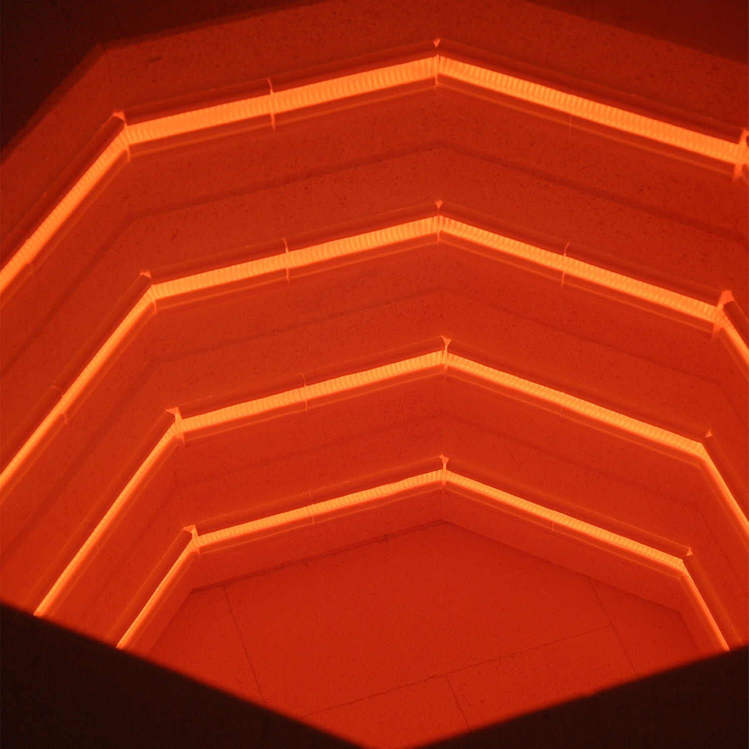
- Heating elements: The heating elements heat the kiln. They are made of a special metal resistance alloy designed to withstand high temperatures and produce heat with a specific amount of resistance.
Control Circuit
- On/Off Switch: The on/off switch only turns the power off to the control circuit.
- Control Fuse: After the on/off switch, a small fuse will break the power to the control circuit if there is a short circuit or too much power is pulled.
- Transformer: This transforms the high voltage from the power source into low voltage to operate the control and the relays. The control typically operates on 24 volts, and the relays on 12 volts.
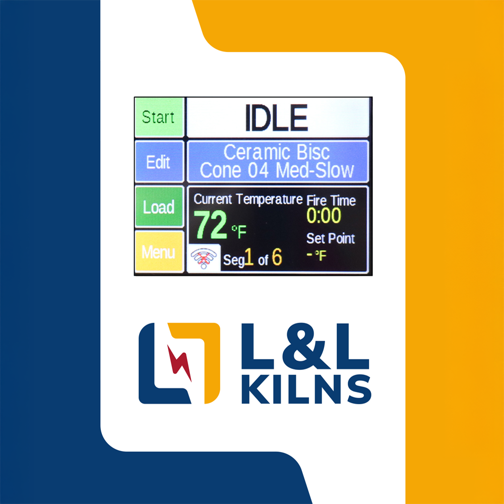
- Temperature controller: The temperature controller receives the temperature information from the thermocouple and adjusts the power supplied to the heating elements to maintain a consistent temperature inside the kiln. Programs are made from ramps (rate of temperature increase), set points (temperature), and holds (duration at the set point in time). Controls can be programmed to go up and down at a programmed rate (as long as the cooling rate is no faster than the kiln's heat loss).
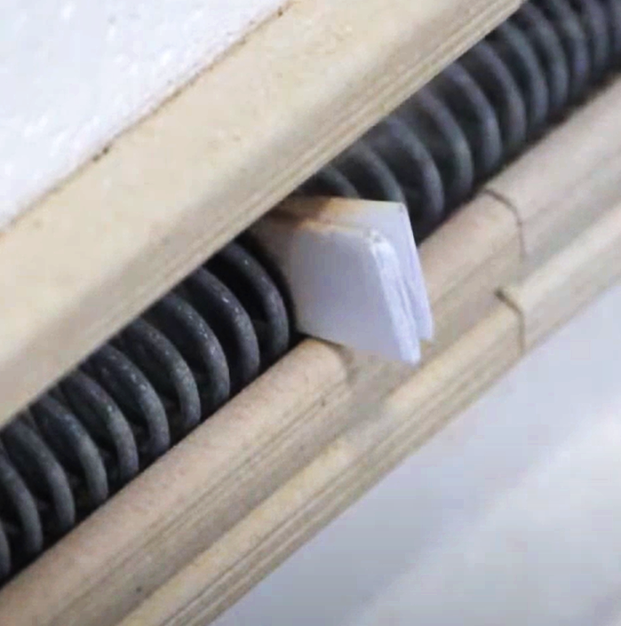
- Thermocouple: A thermocouple is a temperature sensor that measures the temperature inside the kiln. It is made of two slightly different metal alloys. The effect of temperature on these dissimilar metals produces a very low voltage (millivolt) current, which is proportional to the temperature inside the kiln. This millivoltage is transmitted to the temperature control through specially calibrated wires (the thermocouple connection wires). There are different kinds of thermocouples (we use Type K and platinum Type S as an option).
- Contactors/Relays: The control has one or more electronic switches operating the relay's magnetic coil. In the case of SSRs (Solid-State Relays), the signal from the control is a high-speed signal (for the kind we normally use, it is switching at 1/60 of a second compared to a typical 25-second cycle time for mechanical relays).
- Wires and Terminals: For the system to work, all the wires and the places they connect need to be tight and adequately sized.
How a switch (relay) works
- A switch is an electrical device that allows you to control the flow of electricity through a circuit. It can be compared to a valve that can be opened or closed to allow or block water flow through a pipe. In the case of a switch, it can be opened or closed to allow or block the flow of electricity through a wire.
- It consists of a low-voltage coil that gets its signal from the control and a contact that can be moved to either open or close the circuit.
- When the switch is closed, the contact touches the two metal terminals, completing the circuit and allowing electricity to flow through (think of a gate).
- When the switch is open, the contact breaks the circuit, interrupting the flow of electricity.
- The switch's on/off function allows you to control the flow of electricity to the elements.
- Solid-state relays are similar but typically switch on or off at 1/60 a second.
What is a Temperature Control?
- A temperature control works by monitoring the system's temperature or environment using a thermocouple (the little probe that sticks into the kiln).
- If the temperature is too high or too low, the temperature control sends a signal to a control system to take action.
- The control system can adjust the temperature by turning on or off relays, contactors, or Solid State Relays (SSRs).
Why use Zone Control?
- Improved temperature uniformity: Zone control can help achieve a more uniform temperature distribution, which ensures consistent and high-quality results. With zone control, two or three thermocouples control the various zones of the kiln.
- Energy efficiency: By controlling the temperature in three zones, the energy required to maintain the desired temperature can be minimized, resulting in lower energy costs.
- Longer heating element lifespan: Precise temperature control can prevent overheating and thermal cycling, extending the heating element's lifespan.
Series Vs Parallel Element Circuits
- An electrical circuit is a path that electricity can flow through. There are two main types of circuits: series and parallel. Element circuits can be in series or parallel depending on the needs of the design of the kiln.
In a series circuit, the components are connected in a single path, so the electricity has to flow through each component one after the other. Think of it like a line of people holding hands - if one person lets go, the line is broken and the electricity can't flow.
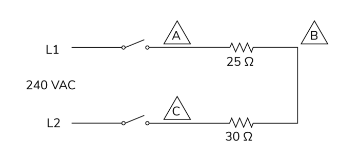
Series Circuits
In a parallel circuit, the components are connected in multiple paths so that the electricity can flow through each element simultaneously. Think of it as a group of people holding hands in a circle - if one person lets go, the circle is still complete, and electricity can still flow through the other paths.

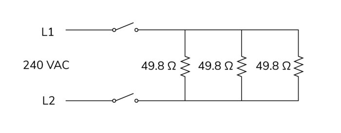
Parallel Circuits
Sometimes, element wiring can be termed series-parallel. Both series circuits get power simultaneously, making them series-parallel circuits.
Series-Parallel
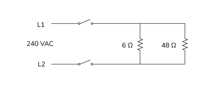
- The main difference between series and parallel circuits is how they affect the current and voltage. In a series circuit, the current is the same through each component, but the voltage is split between them. This means that if one component has too much resistance, it can affect the whole circuit. In a parallel circuit, the voltage is the same across each element, but the current is split between them. This means that if one component fails, the others can still work.
- We use various types of circuits to adapt to the best elements designs.
Why do heating elements age?
- Oxidation: Heating elements react with the air, forming an oxide layer on the surface. Over time, as this layer increases, the element increases in resistance, and less current flows through, reducing the watts (heat).
- Physical wear and tear: Heating elements can become damaged or deformed over time due to exposure to high temperatures, expansion, contraction, or mechanical stress.
- Contamination: If the heating element comes into contact with contaminants, it can become less effective at transferring heat.
- Vent helps: Downdraft venting removes contaminants from the kiln atmosphere and helps maintain the protective oxide coating on the elements.
What is Single Phase vs Three Phase?
- Electricity is generated as three-phase electric power. It uses three different wires to transmit electricity. Each wire carries an electric current that is out of sync with the other cables, which means that the overall flow of electricity is always constant and steady. This helps provide a more consistent and efficient power supply to devices that require a lot of electricity, such as electric motors and large appliances. Three-phase power is commonly used in industrial and commercial settings but can also be found in some residential applications (rarely in the USA).
- Typically, the power you get in a residential area is single-phase. The utility company feeds individual houses with two wires from the three-phase main power line. There is also a Neutral (see below for how this is used).
- Three-phase power uses three "hot" lines, while single-phase power uses two wires.
Delta vs Wye Three-Phase
- For the three-phase “delta,” 208 or 240 volts are measured between two of the three wires, and 120 volts are measured from any hot 240-volt line to Neutral.
- For three-phase “wye” (seen in some industrial installations in the USA and most other countries) 220 to 240 volts is measured from any hot wire and the Neutral.
Electrical Supply Problems and slow kiln performance
- One of the most difficult kiln performance problems to address is a problem with the electrical supply to the kiln. The apparent symptoms might be an Error 1 (E1), sluggish heat up, or poorly fired work.
- Kilns are designed to operate at particular voltages. Typically (in the US), this is either 240 or 208 volts, although it can be 480 volts (mostly industrial). In many non-US locations, 380 volts/220 volts is common. Just because a circuit box is labeled for a particular voltage does not mean it can consistently deliver that voltage.
- A kiln is a large resistive load that will pull a lot of electricity. When you turn the kiln on the voltage will decrease. Voltage can be compared to water pressure. Imagine a full water hose where the nozzle is turned off or down. There is a lot of pressure in the hose, making it rather stiff. When you open the nozzle, the hose goes slack because the pressure goes down. In the same way, when you turn on the kiln, chances are your voltage will drop.
- When the voltage drops the amperage and wattage (power output) will also drop. That means the kiln will get less power than it was designed to get. Most of the time this is not a problem because there is usually enough reserve built into both the kiln and the power supply.
- However, the kiln condition, its load, and the maximum desired temperature, coupled with a power supply issue, can cause a performance drop that creates a noticeable problem.
Kiln Issues
- Some kilns are underpowered because of various constraints. The most common is a 10 cubic foot kiln, like the e28T-3 or any other similar 10 cubic foot kiln, designed to work on a 60-amp circuit. The 60-amp circuit is a common limitation because they are so commonly available, and the cost of making a kiln over 48 amps (the maximum full-load amps for a 60-amp circuit) significantly changes the kiln's price. For instance, an e28T-3 rated at 240 volts is nominally listed for Cone 8 operation, and an e28T-3 rated for 208 volts is nominally listed for Cone 5 operation. Those limits assume a good voltage supply and an average load of no more than about 75 to 100 pounds.
- The point is that with some kilns, you will be operating on the edge. Under some conditions, they will not perform well, and you may have to reduce the size of the load and/or reduce the temperature at which you are firing. The other option is to get a kiln with a higher wattage rating, like a JD2927-3 or an eQ2827-3, or change to a three-phase kiln, where you can get more wattage in a smaller amperage circuit.
- One of the first things to do is switch to single-zone control to ensure that all the available power is going to the kiln.
Power Supply Issues
- Several things can cause low or inconsistent voltage.
- First, you can usually see this by taking voltage readings of the kiln UNDER LOAD (while firing at full speed. To do this, set up a Vary-Fire program with one ramp at 9999 (the fastest it can go) to a set point of perhaps 2000. Vary-Fire program #6 may already be set up this way, so start by looking there. With the control panel open, you can check the voltage of the incoming line at the terminal block. (This should be done by someone knowledgeable about electricity because you will be dealing with high voltages). If you have a problem with your power, you will typically see a significant voltage drop of up to about 5% or sometimes more when the kiln starts to fire. You may even have low voltage when the kiln is not firing, which is only exacerbated by the kiln load. In addition, there may be other significant loads on that same root electrical circuit, like big motors, air conditioners, pumps, and other kilns, that may or may not come on while the kiln is firing and cause voltage drops that you do NOT see at a particular point in time. Be sure to investigate what other large electrical loads might be nearby.
- In addition, at certain times of day (like around dinner time) or in certain seasons (like summer), the entire electrical grid can experience a voltage drop. This can compound whatever issues you may have or the root cause of your problem if it is bad enough.
- Some electricians will tell you that the power grid is supposed to work within a specific range of voltages. This is true in general and generally applies well to motors. Large resistive loads like kilns are unusual and, for some kilns, a voltage drop of 5% will be a problem.
- Long runs of wire from the circuit breaker to the kiln, especially if the wire thickness is just adequate, can cause problems. One of the unusual aspects of a kiln's electrical load is that it may be pulling full amperage for a long period. The thinner and longer the supply wire to the kilns, the greater the resistance to electricity it has. A large resistive load can cause the wire to heat up somewhat, which is not necessarily enough to be a hazard but enough to reduce the wire's amperage carrying capacity (called ampacity). This can cause a voltage drop at the kiln.
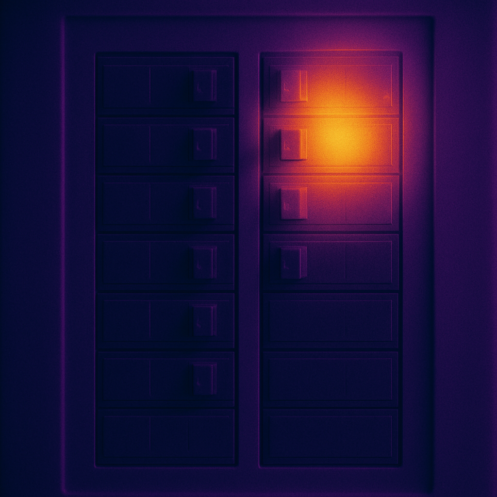
- Another place to be looked at is the circuit breaker that feeds the kiln. If you have one of those inexpensive infrared thermometers, check the temperature of the circuit breaker. If it is hot, the wires going into it may be loosely connected, or the circuit breaker itself might be bad. See the infrared photo for an example of what can happen.
- Some electrical supply systems have a tap transformer supplying them. Your facility manager or electrician may be able to turn up the voltage by changing a tap. Be careful not to turn it up too much and be sure to test the voltage and the amp draw on the kiln before proceeding to operate it.
- Another solution is to install a buck-boost transformer on the kiln circuit. Let's say you have only 195 volts coming into the kiln circuit (under load) and you want 208 volts. You could get a transformer that will boost the voltage from 195 to 208.
- Sometimes, low voltage is enough to heat the kiln but causes the control to misbehave. For instance, 195 volts will not provide the proper voltage to the control. If you are firing a light load to a low temperature, however, you may have enough wattage to do that. There is an easy solution to this problem. You can get a 120-volt separate cord to feed the control transformer. The control transformer that we use has two inputs. One is 240-208. The other is 120. You attach the cord to the 120-volt inputs and plug that into a 120-volt outlet. You can even go one better and get a decent battery UPS computer power supply (about $100) and plug it into that. That can solve other things like intermittent power outages, power supply spikes, electrical noise, etc.
How to handle power interruptions, blackouts, and bad electrical power grids
In some places, the electrical power is very inconsistent with power outages, interruptions, blackouts, voltage spikes, voltage drops, or excessive environmental line noise (such as is caused by large 3-phase motors or phase angle fired SCRs) and other inconsistent noisy electricity. These conditions are found on overburdened power grids, in some factories, and sometimes in rural areas, as well as in many countries. This can cause the computer circuits in an automatic control to produce errors that could affect your firing. See this post for solutions.